GNSS
coordinates


Simulation of Galileo E5 Signal

May 2008 | Comments Off on Simulation of Galileo E5 Signal

Fantinato Samuele

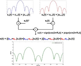
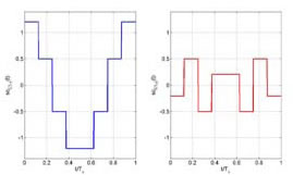
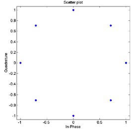
In Galileo AltBOC has been modified introducing two different subcarriers and the products of the components in order to obtain a signal that lies on an 8-PSK constellation (constant envelope) which is very important for satellites high power amplifiers.

artical4_image8

Figure 3 Construction and Power Spectral Density of AltBOC Signal

artical4_image0

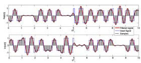
Figure 5 Real and Imaginary part of E5 ideal signal, E5 filtered signal and its samples (K=8)

artical4_image11

Figure 5 Real and Imaginary part of E5 ideal signal, E5 filtered signal and its samples (K=8)

artical4_image12

Figure 6 Constellation of E5 signal

artical4_image14

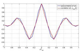
Figure 7 Shapes of autocorrelation of S(t) and correlation between S(t) and Spilot(t)

In the following lines is reported how, in the simulation, the samples of E5 signal are generated, for more details see [11]. As known in AltBOC(n, m), n represent the chip rate of the signal and m the frequency of the subcarriers. As one can see the subcarrier period is Ts = (n/m) Tc = (2/3)Tc. The two subcarriers are defined every Ts/8, so after the multiplexing scheme each chip period is composed of N = 12 slots in which the values of the signal can be different. The components ex– Y(nTc) are then interpolated with a “hold interpolator” of factor N = 12 and so directly multiplexed according to the expression of Eq. 2. The output signal is defined in TAB = Tc/12.
Now is shown the relationship between the chip rate Rc = 1/Tc and the bandwidth in which the signal should be transmitted. The one side bandwidth is B = 25.575MHz that B = 2.5Rc. Now is necessary to select a correct sampling frequency: Fsamp = KB with K > 2. So the ratio between the sample time, Tsamp = 1/Fsamp, and TAB is Tsamp/TAB = 24/5K. For example if K = 4 one have to upsample the signal by a factor 5, filter (In the simulation is introduced a raised root cosine filter with roll-off factor a =0.22) it in order to bandlimiting it, and then sample it with a factor 6 obtaining 10 samples for chip. These equations and values can be important in the development of a software receiver for E5, in particular the value of K determine the sampling frequency and so the resolution of the receiver. The procedure illustrated can be useful in a software receiver for the efficient generation of the local signals for the correlations with the input signal. Real and imaginary part of AltBOC(15,10) signal are in Fig. 5 and its constellation is represented in Fig. 6.

artical4_image15

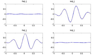
Figure 8 Shapes of correlations r1(t) and r2(t)

Acquisition, Tracking and Data Recovery

As previously said it has been developed a receiver for the demodulation of the overall E5 signal: the signal in input at the receiver is directly sampled (in a simulation the signal is already sampled) and the complex samples are then processed. In the acquisition and tracking process is performed a correlation between the received sampled signal and the samples of a local AltBOC(15,10) pilot signal defined as: Eq.4 This signal can been obtained from Eq. 2 setting to zero the data components ea–I and eb–I and the different normalization factor is introduced in order to not reduce the peak of correlation. In figure 7 one can observe that there is no a significant difference between the autocorrelation of S(t) signal and the correlation between S(t) and Spilot(t). The acquisition is performed using FFT based technique [4] and the delay and doppler frequency are estimated with precision depending on the sample time Tsamp and on the length of correlation. Also for the tracking of the signal the correlation is between the received signal and pilot signal of Eq. 4. For the tracking it is implemented a non-coherent Early minus Late DLL [6].
The data recovery operations use two local sampled signals (Eq. 5 and 6) that are both correlated with the incoming received signal [9]. These signal are obtained setting to zero the pilot components in S(t). This choice is made because using only one signal (Sdata–1(t)) shows a problem when the sign of the two data is opposite: there is a zero in the middle of both real and imaginary part of correlation
Making correlation with these two signals for the decision for the transmitted data is necessary to observe only real parts of the two correlations. For example when the data of component ea–I = –1 nd the data of component eb–I = 1 the shapes of real and imaginary parts of correlations r1(t) and r2(t) between the received signal and Sdata– 1(t) and Sdata–2(t) respectively are in Fig. 8. In the table 2 are summarized all the cases.

Conclusion

In this paper have been described the main features of Galileo E5 signal and some algorithms for signal generation and software receivers. In particular have been highlighted differences between conventional AltBOC and that used in Galileo: two subcarriers are used and the signal has an 8-PSK constellation. Have been given some useful equations for the implementation of a signal generator or the development of a simulation and have been proposed some techniques for the acquisition, tracking and data recovery of the overall received signal.

References

[1] ESA,GJU “Galileo Open Service: Signal In Space Interface Control Document (OS SIS ICD) Draft 0’’, 23-05-2006
[2] G. W. Hein, J. Godet, J.L. Issler, J.C. Martin, P. Erhard, R. L.Rodriguez, T. Pratt “Status of Galileo Frequency and Signal Design’’, Brussels , 2002
[3] L. Ries, L. Lestarquit, E.A. Miret, F. Legrand, W. Vigneau, C. Bourga “A Software Simulation Tool for GNSS2 BOC Signals Analysis’’, 2002
[4] D.J.R. Van Nee, A.J.R.M. Coenen “New Fast GPS Code- Acquisition Tecnique Using FFT’’, ELECTRONICS LETTERS 17th January 1991 Vol. 27 No. 2
[5] K. Krumvieda, P. Madhani, C. Cloman, E. Olson, J. Thomas, P. Axelrad, W. Kober “A Complete IF Software GPS Receiver: A Tutorial about the Details’’, ION GPS 2001, Salt Lake City, 2001
[6] W. Zhuang, J. Tranquilla “Modelling and Analysis for the GPS Pseudo- Range Observable’’, IEEE TRANSACTIONS ON AEROSPACE AND ELECTRONIC SYSTEMS VOL. 31, NO. 2 APRIL 1995
[7] J.M. Sleewaegen, W. De Wilde, M. Hollreiser “Galileo AltBOC Receiver’’, 2004
[8] N. Gerein, A. Manz, M. Clayton, M. Olynik “Galileo Sensor Station Ground Reference Receiver Performance Characteristics’’, ION GPS/GNSS 2003, 9-12 Sept 2003, Portland, OR
[9] N.Gerein “Hardware Architecture for Processing Galileo Alternate Binary Offset Carrier (AltBOC) signals’’, United States Patent, No. 6,922,177 B2, July 2006
[10] M.C. Jeruchim, P. Balaban, K.S. Shanmugan “Simulation of Communication Systems’’, Plenum Publishing Corporation, New York, 1992
[11] S. Fantinato, S. Pupolin, L. Vangelista “Analysis of Galileo AltBOC(15,10) Signal for Simulations and Software Receivers’’, Proceedings of WPMC 2007, Jaipur (India)
[12] S. Fantinato, Thesis: “Development of a software receiver for Galileo system’’, Padova, 2007


Fantinato Samuele Fantinato Samuele: he got a degree in Telecommunications Engineering in July 2007 at University of Padova, Italy, with the top of the marks. He was at “Department of Information Engineering’’. He joined Qascom Srl (an Italian company working in GPS security and authentication), during the thesis period. He is now interested in working in companies researching in navigation and satellite communication systems. samuele.fantinato@gmail.com


My coordinates
EDITORIAL
 
His Coordinates
Steve Berglund
 
News
INDUSTRYLBS | GPSGIS  | REMOTE SENSING | GALILEO UPDATE
 
Mark your calendar
May 09 TO DECEMBER 2009

«Previous 1 2View All| Next»

Pages: 1 2

1 Star2 Stars3 Stars4 Stars5 Stars (No Ratings Yet)
Loading...