Simulation of Galileo E5 Signal
May 2008 | Comments Off on Simulation of Galileo E5 Signal
|
Fantinato Samuele
|

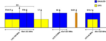
Figure 1 Galileo spectrum allocation
E5 band (1164 -1215 MHz), composed of E5a and E5b bands, is part of the spectrum allocated by ITU for new Radio Navigation Satellite Services in 2000. E5 signal has the wider bandwidth (51.150 MHz) never used in satellite navigation. Galileo E5 signal is composed by two data components and two pilot components broadcasted together by means of the multiplexing scheme AltBOC(15,10). E5a band will be used for Freely/NAV message (Open Service) and the codes of data and pilot components are uncripted, E5b band will be used for Integrity/NAV message for Safety of Life and Open Service. Integrity of signal is probably the most advanced service introduced by Galileo [1]. One of the main feature of E5 band is that the signal can be received in two ways: the first is to filter and demodulate only one of side bands E5a or E5b (see Fig. 1) the second is to process the overall received signal containing the components of both bands [2],[3]. In this sections is considered the second way because it will be adopted by professional receivers and this will avoid to obtain all the advantages of Galileo signal. E5 is the most promising signal in terms of performance in multipath environment and positioning for critical applications but also the most challenging for a receiver or a simulation. In this paper will be presented the simulation of the transmission and reception of E5 signal. It will be first described the generation of codes, then it will be illustrated Galileo AltBOC(15,10) signal structure and its differences with a conventional AltBOC, it will be shown a way for the generation of that signal and some basic characteristics for the development of a software receiver for E5.

Table 1 Feature of E5 components
Simulation
The simulation is developed using Matlab. Four satellites are transmitting Galileo AltBOC(15,10) signal in steps of one millisecond.
For each transmitted signal some effects are introduced like doppler shift due to relative motion between satellite and receiver, delay, multipath channel and gaussian noise and then the overall received signal is processed with some algorithms typical of software receivers. All the blocks are simulated at baseband.
Signal Generation
The first step in the simulation is the generation of Galileo E5 codes. In E5 signal there are four components or channels: , , and . Each component has its own code which is the product of the repetition of a primary code of 10230 chips, corresponding to 1 ms of signal, and a secondary code of different length, see Tab. 1. “Galileo Signal In Space Interface Control Document” (SIS ICD) gives the basis for generation of codes: the primary codes are generated by means of two Linear Feedback Shift Registers. For each satellite SIS ICD gives the “start values” and the values of feedback taps as polynomials in octal notation and some instructions to build correctly the LFSR. The secondary codes are only the conversion in binary representation of a hexadecimal number. Through some Matlab functions primary and secondary codes are generated for all satellites involved in simulation. As known in a Matlab simulation is necessary to define the reference time domain of each signal. The bits of the codes are then mapped in +1 BPSK values producing the discrete signals ex–y(nTc) with Tc 97.75ns that is the chip period. and are data channels with data rate reported in Tab. 1, and so the ranging codes are multiplied by two different data streams, and are pilot channels containing only the ranging codes. In conventional AltBOC the complex signal eb (t) = eb–I (t) + jeb–Q (t) is multiplied by a complex squared subcarrier er (t) = cr (t) + jsr (t) where cr (t) is the sign of a cosine function and Sr (t) is the sign of a sine function and the complex signal ea (t) = ea–I (t) + jea–Q (t) is multiplied by the complex conjugate of er (t), i.e. er *(t) obtaining the signal:

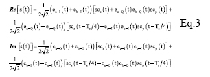
In Figure 3 is represented how an AltBOC signal is built and its power spectral density in which one can recognize the two main lobes that represent the bands E5a and E5b. The Galileo AltBOC(15,10) signal structure is more complex than conventional AltBOC and has expression: where:

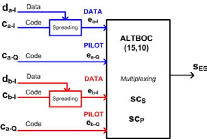
where SCS(t) and SCp(t) are two subcarriers quantized in four values (Fig. 4).

Figure 2 Generation of AltBOC(15,10) signal
|
| |
«Previous 1 2View All| Next»
Pages: 1 2


 (5.00 out of 5)


 (5.00 out of 5)


 (5.00 out of 5)


 (4.99 out of 5)