| Mycoordinates | |
MSAS performance evaluation under ionospheric conditions
|
||||
|
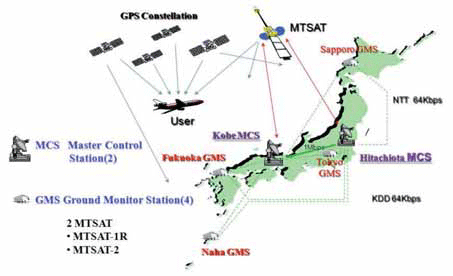
The Multi-functional Satellite Augmentation System (MSAS) is a Japanese Satellite Based Augmentation System (SBAS) [1] which provides Differential GPS (DGPS) corrections and is designed to supplement GPS by reporting and monitoring the reliability and accuracy of GPS signals in real time. MSAS consists of two satellites, (MTSAT-1R at 140E longitude and MTSAT-2 at 145E longitude), four Ground Monitor Stations (GMS), two Master Control Stations (MCS), and two Monitor and Ranging Stations [1]. The MSAS architecture is shown in Figure 1. Although it is designed for aircraft, the signals also can be received and used on land and sea. The primary MSAS coverage area includes a wide signifi cant range of latitude (25N to 45N in geographic latitude; 15N to 35N in magnetic latitude) [2]. Similar services are provided in US by the Wide Area Augmentation System (WAAS) and in Europe by the European Geostationary Navigation Overlay Service (EGNOS). Through the use of SBAS, an individual GPS receiver is able to remove correlated errors from its measurements and thus, obtain much better accuracy. The aim of this study is to evaluate MSAS performance under severe ionospheric conditions that were observed from 2001 to 2003, when the ionosphere was more active because the 11-year solar cycle was near its peak. Single-Frequency PPP (SF-PPP) was used instead of using MSAS correction data because MSAS was not yet fi elded during the above period. Another reason that Single-Frequency PPP for was used for our evaluation was that the performance of MSAS and SFPPP was approximately same in terms of theoretical error models. Many papers have been published for both Single- Frequency and Dual-Frequency PPP algorithm, while several papers related to pseudo-range based Single-Frequency PPP have also been presented [3]. In Section 2, the relationship between GNSS and solar activity is briefl y described. In Section 3, the outline of MSAS and Single-Frequency PPP are described from the view point of error models. In Section 4, the actual performance of MSAS and SF-PPP were verifi ed using raw data from 2008. From this data, it is found that, as expected, MSAS and SF-PPP performance were approximately the same. SF-PPP positioning performance was then investigated using raw data from 2001 to 2003, during the active solar period.
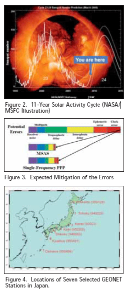
Figure 1. MSAS System Architecture GNSS and solar activity It is well-known that ionosphere is the largest error source in positioning for single-frequency GNSS users. Since solar activity has a strong correlation with ionosphere activity, positioning error can increase signifi cantly at low latitudes (and elsewhere, to a lesser degree) during periods of increased solar activity. During these periods, ionospheric delays at the L1 frequency are normally 5 to 15 meters in the zenith direction, and the delay can reach 100 meters at peak periods. Figure 2 shows the typical solar cycle given by NASA (http://weather.msfc.nasa.gov/). Major ionospheric effects correspond to the rise and fall in the number of sunspots. At present, we are in near solar minimum. In this paper, MSAS performance during solar maximum is estimated by using raw data from the previous solar maximum. Error models [4] For standalone GPS point positioning after the deactivation of Selective Availability (SA) in 2000, the dominant error sources consist of satellite orbits and clocks and, ionosphere and troposphere delays, resulting in 2serrors of about 10 meters horizontally and 15 meters vertically. Satellite orbits and clock corrections are broadcast inside the GPS navigation messages and are typically accurate to 1 – 3 meters. Ionospheric delay varies with time and season up to 15 – 30 meters at zenith and is about 3-4 times larger at low elevation angles. Using the Klobuchar ionospheric model together with the parameters included in the navigation messages can remove about 50 % of the ionospheric delay. The other part of the atmosphere, the troposphere, causes a delay of about 2.5 meters at zenith and can be as large as 20 meters at a low elevation angle. However, this can be reduced greatly by using one of the various tropospheric models. In the following sections, two approaches to reduce these errors are shown. The fi rst method is MSAS, and the second method is Single-Frequency PPP. In this paper, only pseudo-range measurements and corrections are used for MSAS and Single-Frequency PPP positioning. MSAS [5] In order to support a large service area, MSAS provides vector correction information, which consisting of separate correction messages that include satellite clock, satellite orbit, and ionospheric propagation delay. The MSAS 250-bps message contains an 8-bits preamble, a 6-bit message type ID, and a 24-bits CRC parity check code. The remaining 212 bits are defi ned with respect to each message type. When we look at the messages to correct user errors models, several message types are particularly important. Message Types 2-5 contain fast corrections to satellite clock that are updated frequently. Message Type 25 contains long-term corrections to satellite orbit and clock. Message Type 26 provides ionospheric corrections by specifying the MSAS-estimated vertical delay in meters at ionospheric grid points (IGP) located every 5 degrees in latitude and longitude. User receivers perform spatial bilinear interpolation and verticalto- slant conversion using algorithms defi ned by the SBAS SARPs to obtain the estimated line-of-sight delay at the nearby user’s ionospheric pierce point (IPP) [6]. For SBAS, tropospheric correction is not broadcast; hence they are computed using a pre-defi ned model. Averaged meteorological parameters are used for this tropospheric correction, and a simple mapping function is used to calculate the line-of-sight tropospheric error.
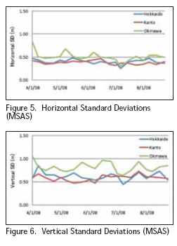
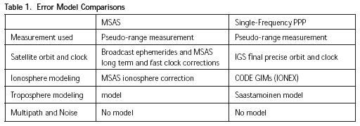
Single-Frequency Precise Point Positioning (PPP) [3] Since 1994, The International GNSS Service (IGS), has been providing several types of precise satellite orbits and clocks, including Ultra Rapid, Rapid, and Final ephemerides. They are different in latency and accuracy but have the same sampling interval of 15 minutes. The “Final” product was used in this paper because it has the best performance. Its accuracy is within 5cm and 0.1 ns in both the satellite orbit and the satellite clock. All these products are distributed in SP3 format in which combined satellite positions and clocks (http://igscb.jpl.nasa. gov/components/prods.html). In order to correct for antenna phase-center offset, estimates of the offsets in each satellite were obtained from the internet (ftp:// igscb.jpl.nasa.gov/pub/station/general/). As noted earlier, the ionosphere is the dominant source of error after the elimination of S/A. Although dualfrequency users can easily resolve this problem by directly estimating ionospheric delay, ionospheric models still need to be developed for single-frequency users. Since 1996, Global Ionospheric maps (GIMs) have been available from the Center for Orbit Determination in Europe (CODE). In GIMs, the total electron content (TEC) of the ionosphere is given as a 2-dimensional map that is supplied in IONosphere map EXchange (IONEX) format. The resolution of the map is 5º in longitude and 2.5º in latitude. Each daily IONEX fi le contains 13 maps with 2-hour time spacing (ftp://ftp.unibe.ch/aiub/ CODE/). From GIMs, only the vertical TEC (VTEC) can be derived. Hence, a mapping function is deployed to map the vertical TEC value to the slant TEC value. This technique is based on a singlelayer model which models the ionosphere as a shell of infi nitesimal thickness. Although the accuracy of ionospheric estimation strongly depends on the solar activity, the standard accuracy is within a decimeter under quiet solar conditions. The Saastamoinen model was used to estimate tropospheric delay in this paper [4]. This model was derived using gas laws and simplifying assumptions regarding changes in pressure, temperature, and humidity with altitude and estimates two separate components of tropospheric delay. The “dry delay” in the zenith direction comprises most of the delay and can be predicted with an accuracy of a few millimeters from accurate surface pressure measurements. The smaller “wet delay” depends upon the distribution of water vapor along the signal path and is much more variable. Use of average meteorological conditions rather than actual measurements introduces additional modeling errors in both dry and wet delays, resulting in a total zenith delay error of 5-10 cm. One of the mapping functions was used to calculate the lineof- sight tropospheric error [4]. In this paper, L1-L2 biases are compensated because satellite orbits and clocks always refer to the ionosphere-free linear combination between L1 and L2 codes. Comparisons Table 1 shows an error model comparison between MSAS and Single-Frequency PPP. There are few differences for the error models regarding accuracy. Figure 3 shows the expected degree of error mitigation for both methods. To generate Vertical TEC (VTEC) corrections, MSAS uses 6 sites in Japan and GIMs uses fewer. From a theoretical point of view, MSAS performance should be slightly better than Single- Frequency PPP, but Single-Frequency PPP can be used to estimate MSAS performance with fairly good accuracy.
Testing and results First, MSAS performance during the recent solar-minimum period was evaluated. Single-Frequency PPP performance was also evaluated using the same period fro comparison. Next, Single-Frequency PPP performance was evaluated using raw-data from the solar-maximum period. Finally, dual-frequency-based ionospheric error estimation was tested using the raw -data from a known large solar-fl are event. |
Pages: 1 2


 (No Ratings Yet)


