| My News | |
GPS/GNSS signals multipath modeling
|
|||||||||||||||
| GPS ranging is based on the reception of the LoS component of the signals transmitted from the constellation of GPS satellite vehicles (SV), and on measuring the time elapsed in the propagation of appropriately time-marked signal signatures. Even in the absence of any reflected (multipath) signal components, the determination of physical separations between SVs and receiver is tied to a subtlety arising from the relative motion between the two –Doppler effect. The Doppler effect can be approximately represented by a shift of the transmitted signal spectrum toward higher or lower frequencies along with an increase or decrease in the modulation (code) signal bandwidth, respectively for the cases when transmitter and receiver are approaching or receding from each other.
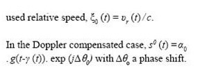
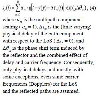
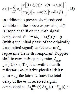
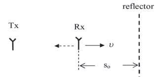
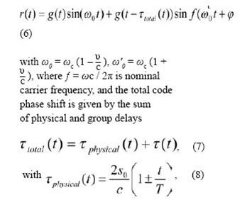
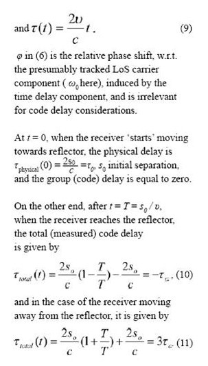
By the process of demodulation routinely performed in GPS receivers, the motion-induced spectral shifting is essentially compensated for, and the (remaining uncompensated) correlation peak positions tracked by Delay-Lock Loop (DLL) can be directly related to physical distance(s). The latter is done by multiplying the pertaining time delay by the speed of light, c, apart from correcting for ionosphere & troposphere propagation effects, clock corrections, and along with accounting for the navigation solution related SVs ephemeredes, earth rotation, etc. Without such Doppler correction/tracking, the measured propagation delay would differ from the actual physical separation (say, at the time of transmission) by the group delay accumulated during the pertaining signal (energy) transition time. This in turn suggests that at every time instant the total measured delay based on Doppler shift uncompensated signal correlation peaks, or on the ranging signal markers, equals the algebraic sum of the physical delay (always positive), and the group delay accumulated up to the time of reception, which can be positive or negative, depending on the sense of relative motion. This can be described implicitly by the so-called ‘code ranging formula’ Even with the LoS component undisturbed by multipath reflections, a ‘poor’ GPS receiver design can ensue, either because the pertinent signal propagation model is not correctly interpreted (this applies to the SV constellation signals modeling as well), or because the code tracking loop is too ‘heavy-driven’ by the carrier tracking loop control signal. As the traditional multipath modeling having been in use since the very GPS inception totally ignores the LoS relative multipath code Doppler resulting from the multipath components themselves having carrier Doppler shifts differing from the LoS one, the question is what all could be the repercussions in situations involving receiver and/or reflectors mobility?! The chance that the vehicle moving in an urban-canyon area gets directed and even ends-up ‘into a ditch’, or that the aircraft shows unable to autonomously perform the Category II/III landing may be substantially increased, if one strictly follows the ‘conventional wisdom’, or de-facto ‘GPS Dogma’ that the first detectable correlation peak has to be the LoS one, or that all measured multipath delays have to be positive ‘by definition’. Multipath modeling–static versus dynamicActually, in GPS/GNSS there is no such thing as an entirely static scenario. Even in the static receiver case (non-moving vehicle), in the ubiquitous presence of nearby reflectors, there is a slight (mostly sub-Hz) difference between the Doppler shifts on LoS and the reflected multipath components due to SVs motion and resulting time varying reflection angles. Still, for almost all practical purposes, except perhaps for the sub-cm accuracies, this can be considered as a static case. With low and moderate vehicle speeds of some tens of mi/h, depending on the time duration of reflection presence or its existence before the receiver is exposed to it, the generally un-modeled code Doppler effects can be of great importance. This is the more so since the resulting (LoS-relative) multipath carrier Doppler shifts (up to a few 100Hz) may remain insufficiently attenuated by coherent correlations, which due to practical implementation constraints may not be much longer than 20ms. Traditionally, even for dynamical situations, the multipath is modeled through just the modification of the signal’s complex envelope in the (LoS Doppler corrected) form If, for example, the LoS component is fully attenuated, and there exists only one reflected component with the level sufficient to allow for signal acquisition and subsequent tracking, the signal would be ‘regularly’ demodulated by the reflected signal Doppler frequency, and consequently the measured code delay would correspond to the total (presumable LoS, plus relative reflection) physical delay. Apart from the wrong delay and Doppler measurements, there would essentially be no added delay from the code delay accumulation. However, if the LoS is present with its nominal level, and the receiver keeps acquiring and tracking it, the remaining Doppler on the reflected components stays uncompensated, and the corresponding multipath correlation peaks exhibit additional group delay terms in addition to their relative physical delay terms, Δτm, or the τphysical term, as per (2) & (3). Consequently, the multipath modeling in environments with a moving receiver and/or reflectors takes the form This analysis suggests that the code-phase terms should be explicitly modeled in software and hardware simulators for each separate path (or delay-line tap) in accordance with the corresponding Doppler shift. The parameters’ dynamics should be inferred from measurements carefully conducted to capture this effect in a number of typical scenarios. Evaluation in simple two-path scenariosFor the sake of illustration, we evaluate the underlying Doppler to code-phase conversion using the total measured delay of the reflected component with respect to the LoS, a part of which is the group delay in equation 2. The simplified scenarios are shown in Fig. 1 and Fig. 2, with so the separation at t = 0. To relate these to the model in (3), here m=1, and transmitter is assumed to be fixed. The received signal consists of a sum of LoS and the reflected component
Fig 1 – Mobility scenario I – fixed reflector and transmitter.
Fig 2–Mobility scenario II – fixed receiver and transmitter, and moving reflector.
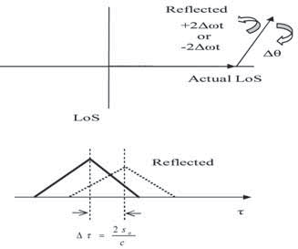
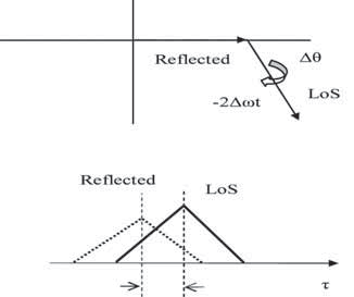
This suggests that the LoS ‘barrier’ gets‘ broken-through’, and consequently the reflected component comes ahead of the LoS one. In this simplified scenario the advancing of the reflected code correlation peak over the LoS one starts after the initial physical separation is halved, at t = T / 2, when the LoS and the reflected peak positions coincide. Essentially, this effect takes place at all relative vehicle speeds, so that it is in fact the product of relative Doppler shifts and the duration of the receiver exposure to the reflected, i.e. the ‘deformed’ field, that determines the actual departure of measured code phase with respect to the LoS component’s code phase. Of course, this is by no means in violation of the currently valid physical principles – we are not talking here about the electromagnetic energy propagation, but rather its group propagation, and it is a well known fact of physics that the light group speed of propagation can be measured as either higher or lower, and even negative w.r.t the speed of light propagation constant c, depending on the dispersivity features of the transmission medium. To provide some quantitative indications for the possibility that the reflected path correlation peak position itself can ‘breakthrough’ the LoS ‘barrier’, the following examples are given: For a medium dynamical situation take υ = 50km/h, S0 =15m, τ0 = 0.1/us, and T =1.08s; these values produce 0.1/us of maximal code advance, i.e. 0.4/us of maximal total code delay, respectively in cases when the receiver is moving toward reflector, and away from it. In the case of only a 10ms long coherent integration, the resulting constant Doppler shift (w.r.t. LoS) of 146Hz results in only up to 13.3 dB of the sin(x)/x attenuation. For a low mobility scenario – υ = 6.5km/h, s0=75m, τ0 = 0.5/us, and T=40s produce the respective maximal code advances and retardations of 0.5/us 1.5/us, the related correlation peaks remaining essentially un-attenuated (1dB at 13.5Hz) even with the coherent integration interval time as long as 50ms. In these scenarios the maximal negative delay happens at the instant when the vehicle ‘hits’ the reflector; while for an experimental set-up this could still be feasible, in a practical situation the reflector can actually be ‘nearby-passed’, or ‘nearby-passing. Typical real-life situations of this kind would be reflections from vehicles moving in the opposite direction, and aircraft landing, for example. Relative Doppler and code phase relationships between the LoS and the reflected signal components can similarly be evaluated in the case of a fixed receiver position and a moving reflector. Although the relative speed between LoS and reflected path is the same, a very important distinction here is that the accumulated code phase difference may be fully independent of the duration of the receiver’s exposure to the reflected signal field, but may rather depend on the time interval over which at a particular location the (compressed or dilated) reflected electromagnetic field had been ‘taking place’, no matter how short the receiver exposure to the reflected signal electromagnetic field might be, provided it is long enough to reliably measure the pertinent code phase. The corresponding scenario is shown in the figure 2. The received signal again consists of a sum of LoS and reflected components in (6), with Repercussions on receiver operationsFollowing the acquisition of the LoS component in the figure 1 example, the tracking process can be described by the phasor diagram of Fig. 3a, with the reflected path’s phasor moving by ( ± 2Δ ωt ( Δω is the LoS relative Doppler shift) around the (ideally) zero-phase (in PLL case) actual LoS component. Half way to the reflector, the reflected component may take control over both tracking loops. When the reflector is reached by the receiver, the tracking situation is described by Fig. 3b – with LoS now rotating over the reflected signal’s phasor.
Fig 3a – A situation where LoS component is tracked.
Fig 3b – A situation with reflected component tracked. In various situations involving accelerations and highly time-varying ratios of the LoS and reflected components’ levels, the dynamics and stability of tracking loops may be affected in many diverse ways. The use of an enhanced multipath model of the kind proposed here is important for the acquisition and tracking strategies and designing effective multipath mitigation algorithms for operations in urban-canyon environments, pedestrian and jogging applications, avionics, guided weaponry, miniature autonomous systems, and other dynamical environments. In summaryThis article presented some considerations regarding a due extension and enhancement of the traditional modeling of multipath in Urban-Canyons and other dynamical environments containing Doppler shifts on reflected signal components that are generally different from the LoS Doppler. An extended model has been derived and some simple illustrative scenarios have been evaluated. The impact of the code group delays on GPS/GNSS receiver tracking loops has been discussed in qualitative terms. An adaptation of the paper presented at the International Symposium on GPS/GNSS, November 11-14, 2008, Tokyo; and also can be found in the Proceedings of the IEEE Aerospace Conference, March 7-14, 2009, Big Sky, Montana, U.S.A. |
|||||||||||||||
|
|||||||||||||||
|





 (No Ratings Yet)


Leave your response!