| GNSS | |
Galileo BOC(1,1) Signal Tracking
A design and implementation of GPS/Galileo software receiver is discussed |
|
There are lots of needs for a unified platform that allows efficient GNSS (Global Navigation Satellite System) receiver development and testing for various applications. With the current functionality of the GPS constellation and the promise of the future Galileo constellation, many efforts have been focused on the 1575.42MHz L1 signals for the GNSS software receiver implementation. GPS (Global Positioning System) L1 or Galileo E1, particularly when coupled with SBAS (Space Based Augmentation System) such as WAAS (Wide Area Augmentation System) or EGNOS (European Geostationary Navigation Overlay System) are likely to fulfill the most navigation needs including accuracy and integrity. Particular interest to receiver researcher is the open service BOC(1,1) (Binary Offset Carrier) modulation format to be transmitted by Galileo at the E1 frequency. Recently MBOC(6,1,1/11) (Multiplexed BOC) is considered as base signal for both Galileo and GPS III. In preparation for mass product receiver before the transmission of the first Galileo signals from satellite, development of GPS/Galileo receiver, capable of tracking the basic BOC(1,1) signals, has been initiated. Bump jump (or known as Very Early – Very Late) correlator, Non-coherent processing in SSB(Single Side Band), Deconvolution correlator and correlator with dual discriminator are well known method to acquire and track correct peak.
In order to develop and test the GNSS signal processing algorithms such as signal acquisition and tracking, a generalized GNSS IF(Intermediate Frequency) signal generator has been designed. The signal generator is capable of processing the wide bandwidth necessary to the Galileo BOC(1,1) signal. This signal generator generates digital samples in the host computer for the software receiver test. Many GPS software receivers have been already implemented in C language by many research groups and they are capable of performing GNSS satellite acquisition and tracking on both real and simulated GNSS data [1]. In this paper, the design and implementation of GPS/ Galileo software receiver is given. The GPS software receiver already working in our laboratory is extended to GPS/ Galileo software receiver. The BOC(1,1) signal acquisition and tracking method and its performance are emphasized.
GPS and Galileo signal characteristics
The GPS C/A code is a binary phase shift keying (BPSK) signal with a chipping rate of 1.023 MHz. The notation BPSK(fc) is used to describe the signal, where fc represents a factor of 1.023MHz[2]. The Galileo Open Service signal on L1 will use a BOC modulated signal. For BOC signals, the spreading code is mixed with a square wave at a given subcarrier frequency. The notation BOC(fs, fc) is used, where fs represents the square wave subcarrier frequency in units of 1.023 MHz, and fc represents the chipping rate in units of 1.023 MHz. The generation of a BOC(1,1) signal is shown in Figure 1, where the top line is a 1.023 MHz square wave, the middle line is a 1.023 MHz spreading code, and the bottom line is the resulting BOC(1,1) modulation signal.
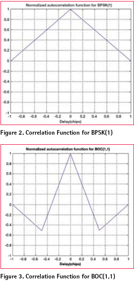
The normalized ideal autocorrelation function for a BPSK(1) signal is shown in Figure 2. The autocorrelation function for a BOC(1,1) signal is shown in Figure 3. Compared to the BPSK(1) autocorrelation function, the square wave subcarrier modulation used with BOC(1,1) causes the autocorrelation function to have a sharp main peak, and two smaller negative side peaks. The sharp main peak will result in improved code tracking performance for the BOC(1,1) signal, as well as improved multipath mitigation performance.
To generate the BPSK(1) and BOC(1,1) signals in software receiver, the GNSS IF signal generator developed by CSLab in Chungnam National University has been used. The power spectral density of generated GPS L1 C/A signal is shown in Figure 4. The generated GPS L1 C/A signal includes C/A code and navigation data messages. All available PRN number can be included in this signal and the navigation data derived from real receiver or a GPS simulator is applied to generate navigation message.
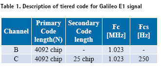
Figure 5 shows a block diagram of tiered signal generation for Galileo E1 signal. At that figure, fc and fcs mean the primary and secondary code chip-rate respectively, and the relation, fcs = fc / N, is satisfied. The detail description for this signal can be found in Table 1 [3].
The power spectrum of generated Galileo E1 signal is shown in Figure 6. It includes ranging code such as primary code and secondary code, and subcarrier for BOC(1,1) modulation. 50 primary codes in the Galileo OS SIS ICD (Open Service Signal In Space Interface Control Document) are applicable to this signal, same as secondary code.
Software GPS/Galileo Receiver
Due to the conceptual similarity of Galileo and GPS, the high-level architecture of Galileo receiver is similar to that of GPS receivers. The essential new element of the new GPS/Galileo receivers is a generic channel, which is able of tracking all the possible modulation schemes including GPS C/A, L2C and Galileo BOC(1,1). The baseband chipset of future GNSS receivers will represent a matrix of generic channels. Future receivers built based on this concept, shall use flexible allocation schemes of channels to incoming signals.
The block diagram of the generic channel is presented in Figure 7 [4]. One of the main differences between the current C/Acode signal and the Galileo signals is the presence of a data-less pilot signals in parallel with the data-bearing signal. With the channel architecture shown in Figure 7 both the pilot and data components can be demodulated in parallel.
The demodulation works as follows. The residual carrier (Doppler) is removed by mixing the incoming signal with a digitally generated complex carrier in carrier mixer. The spreading codes for pilot and data are generated by two code generators, which can be configured to produce any Galileo or GPS spreading code. Thanks to the coherence between the pilot and data components, a single Code DCO controls the rate of both codes. This unit also can control the rate of the (flexible) subcarrier needed for BOC modulation. The same sub-carrier can be used for pilot and data signal. In normal mode both locally generated signals enter two delay lines. The time-shifted signal replicas created in this way are correlated with the incoming signal, producing all correlation values needed for code and phase tracking.
To detect and track a correct-peak in the correlation function, the bump jump algorithm is added in receiver software. The algorithm assumes that the receiver processing includes a code tracking mechanism which accurately tracks some correlation peak whenever the signal-tonoise ratio is high enough. The purpose of this algorithm is to determine whether or not the peak being tracked is the correct one. This is done by comparing the amplitude of the current (prompt) peak with the amplitudes of the neighboring peaks. Thus, it is assumed that there are very early (VE) and very late (VL) samples separated from the prompt (P) sample by a time very close to half the inverse of the offset carrier frequency, i.e., one peak apart. If the VE or VL samples are consistently higher than the P samples, then the tracker will jump in the appropriate direction [5].
The implemented algorithm accomplishes the amplitude comparison with the help of a simple up/down counter as in Figure 8. After each integrate-and-dump period, the absolute values of VE, P, and VL in-phase samples are compared. If either the VE or VL sample is the largest, then the appropriate counter is incremented and the other one is decremented. If the P sample is the largest, then both the VE and VL counter are decremented. Neither counter is decremented below zero, when any counter reaches a particular threshold, T, the tracker is jumped to the new peak, and the counters are reset to zero.
 and late (L) samples are working properly and all the quadrature components are near zero. If that is not appropriate, then a comparison can be made among IVE 2+QVE 2, IP 2+QP 2, and, IVL 2+QVL 2. If this is necessary, signalto- noise performance may suffer degradation
Test Results
Test has been done to evaluate the effectiveness of the GPS/Galileo receiver. Because the Galileo receiver does not perform navigation yet, performance of signal acquisition and tracking is examined, and noise performance of code tracking loop have been analyzed. Setup for these tests is given in Figure 9. Three modules are used to evaluate the performance; IF signal generator, software receiver in C++ and evaluation program in MATLAB.
Signal Acquisition and Tracking
The performance for signal acquisition and tracking is confirmed by the signal power (I2 + Q2). As shown at Figure 10 and Figure 11, both signals had been acquired and they are tracked without interruption to the end of measurements.
Code Tracking Noise
In this section we derive an approximate expression to predict the code tracking performance that can be expected by using BPSK(1) and BOC(1,1) modulation scheme. The receiver implemented in the paper used a dot-product discriminator for the code tracking Delay Lock Loop (DLL).
The approximate expected 1-sigma code tracking performance of the BOC(1,1) modulation using a dot product discriminator is [1]
The Galileo BOC(1,1) receiver, with a dot product discriminator as implemented in this paper, should offer a code tracking improvement of ![]() over BPSK(1) (where 3 is the ratio of the slope of the BOC(1,1) main correlation peak to the BPSK(1) peak).
over BPSK(1) (where 3 is the ratio of the slope of the BOC(1,1) main correlation peak to the BPSK(1) peak).
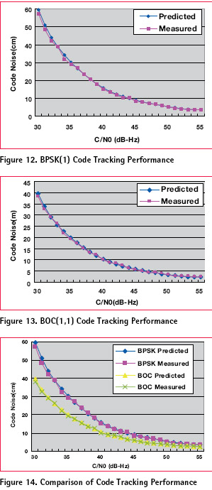
The signal generator and receiver were set to track BPSK(1) and the C/No was varied over time. The receiver was set up to output code measurements, which were logged by the host computer. The test was run once for the data channel only. Figure 12 shows the measured results from the receiver for BPSK Data along with the expected value calculated using equation (2). As can be seen from Figure 12, the measured results agree with the expected results very well.
A similar test was completed for BOC(1,1). The expected performance was calculated using equation (1). The measured and expected results are shown in Figure 13. Again, the measured results from the receiver agree very well with theory. The results from Figure 12 and Figure 13 are plotted together in Figure 14 to emphasize the performance improvement of BOC(1,1) over BPSK(1). The improvement in pseudorange code tracking performance is approximately a factor of ![]() , as predicted earlier. The results of experiments show that implemented signal generator and software receiver are correctly working.
, as predicted earlier. The results of experiments show that implemented signal generator and software receiver are correctly working.
Conclusions
In this paper, a design and implementation of GPS/Galileo software receiver is given. The exisitng GPS receiver which can perform every function of receiver such as acquisition, code and carrier tracking, navigation bit extraction, navigation data decoding, pseudorange calculations, and position calculations is extended to GPS/Galileo receiver. The combined receiver can handle GPS C/A, L2C and Galileo BOC(1,1) signal. A dump jump method to acquire and track the Galileo BOC(1,1) signal is implemented to avoid false tracking. The performance evaluation using GPS/Galileo IF signal generator and software receiver with BOC(1,1) signal tracking feature show that the implemented software receiver can be applied to GNSS receiver design and implementation. Currently, the navigation facility using Galileo signal and Galileo L5 signal processing are further researched by our group.
References
1) Neil Gerein, “Galileo BOC(1,1) Prototype Receiver Development,” ION GNSS 17th International Technical Meeting of the Satellite Division, Long Beach, CA, Sept. 21-24, 2004.
2) IS-GPS-200, Navstar GPS Space Segment/Navigation User Interfaces, December, 2004.
3) European Space Agency, Galileo Open Service Signal In Space Interface Control Document(OS SIS ICD) Draft 0, 2006.
4) Andrew Simsky, “Galileo Receiver Development at Septentrio,” ENC GNSS 2005, Munich, Germany, July 19-22, 2005.
5) Paul Fine, “Tracking Algorithm for GPS Offset Carrier Signals,” Proceedings of the National Technical Meeting of the Institute of Navigation(ION-NTM ‘99), San Diego, California, USA, January, 1999.
 |
|
||||||
 |
|
|||||
 |
|
||||||
My Coordinates |
EDITORIAL |
|
His Coordinates |
|
|
News |
INDUSTRY | GPS | GALILEO UPDATE | LBS | GIS | REMOTE SENSING |
|
Mark your calendar |
JANUARY to SEPTEMBER 2008 |


 (No Ratings Yet)


Leave your response!