| Positioning | |
Evaluation of High Sensitivity GPS Receivers
The performance of the receivers from different manufacturers varies – one receiver may perform very well in one aspect, but not that as well against other criteria. There is no single clear “winner” on the HSGPS receiver market. |
|
 |
|
|||||
 |
|
|||||
 |
|
|||||
 |
|
|||||
The year 1978 saw the launch of the first Global Positioning System (GPS) satellite. Today, GPS, as the first and currently only operational global navigation satellite system (GNSS), is widely used and is a vital technology for many of society’s economic, scientific and social activities. Applications can be found everywhere, such as spacecraft navigation, geodesy, surveying and mapping, precision navigation, machine guidance, vehicle fleet management and “intelligent transport systems” (ITS), emergency services and “location based services” (LBS). Clearly the development of GPS has revolutionised what are now termed “positioning, navigation and timing” (PNT) activities. Although GPS will soon be joined by the next operational GNSS – Russia’s GLONASS, as well as two future competitors – Europe’s GALILEO and China’s COMPASS – GPS dominates the world GNSS market. This is especially the case as far as the mass market ITS and LBS applications are concerned. All new smartphones have a built-in GPS chipset.
GPS works fine everywhere where there is clear sky, so that at least four direct (line-of-sight) GPS signals can be received. However, in many difficult signal environments –where the satellite signals are weak (-172dBW) and multipath is severe, such as urban canyon and indoors – a conventional GPS receiver often fails. So-called “high sensitivity” GPS (HSGPS) receivers have been developed to improve PNT availability under difficult signal environments. In addition, many HSGPS receivers accept “assisted GPS” (A-GPS) messages in order to reduce the time-to-first-fix (TTFF) and possibly increase the sensitivity even further. There are a number of HSGPS receivers available on the market, and their performance, in terms of TTFF and accuracy, does vary.
After a brief review of HSGPS receivers and A-GPS principles, this paper evaluates several HSGPS receivers: ublox LEA-4P, Navman Jupiter 32, ublox EVK-5H and SiRF GSCI-5000. Several tests were carried out, one is a static test, for which an Open Source GNSS Reference Server (OSGRS) was used to provide the A-GPS assistance messages. Kinematic tests were also conducted, in which the receivers were installed on a car to test their performance in urban canyons. Several mobile phones, e.g. Nokia N95, HP iPaq 914c, iPhone 3GS and iPhone 4, were also tested. The TTFF, positioning accuracy and the sensitivity to weak signals was investigated.
High Sensitivity GPS and Assisted GPS
There are two fundamental operating modes of GPS receivers; the first is normally termed “acquisition”, and the second is “tracking”. The latter then enables “positioning” if enough satellites (a minimum of four satellites in the case of 3D positioning) can be tracked, providing a position, velocity and time (PVT) solution. A receiver will remain in this state until it is either turned off or cannot track enough satellite signals.
In the acquisition mode, (if no assistance data can be obtained) the receiver first assumes that a satellite is visible and a channel is allocated for this satellite. There are two search unknowns: the exact frequency of each satellite carrier frequency which is changed by any Doppler shift, and the alignment of the receiver and transmitted pseudo-random number (PRN) codes [1]. The Doppler frequency shift is caused by the relative movement of the receiver and the satellite, as well as any drift in the receiver oscillator. Since the Doppler is unknown, the receiver must search across a wide frequency range, typically 30 or more Doppler “bins”. If using time-domain acquisition, the receiver will try to align the local PRN code generated by the receiver with that transmitted by the satellite. It typically takes one or more seconds to search each Doppler bin [2].
After a satellite signal has been acquired, it can be tracked and the receiver decodes the broadcast navigation data: the time, the orbit ephemeris, the almanac, and other data. The almanac is used to identify the locations (and Doppler shifts) of the other satellites in the GNSS constellation. The ephemeris of each satellite must be obtained to calculate a PVT solution. It takes between 18 to 30 seconds (depending on the start point for decoding) to extract the ephemeris information from the modulated navigation message. However, if there are signal dropouts or loss of any data bits in the message, it takes a much longer time to extract the complete navigation message. In a very difficult signal environment it may even be impossible to perform this decoding operation in a conventional GPS receiver.
GPS signals are very weak when they arrive at the Earth’s surface. The transmitters on the GPS satellites only deliver 27W from a distance over 20,000km in orbit above the Earth. By the time the signals arrive at the user’s receiver, the maximum received signal level is not expected to exceed -153.0dBW, and typically is as weak as −158.5dBW [3]. This is well below the thermal noise level for the signal bandwidth. The received signal strength can be classified into three categories [4]:
• Strong signal strength: > -172dBW. Receivers have a clear view of the sky, operating in open fields or in low rise residential areas.
• Weak signal strength: -172dBW to -180dBW. Environments are very noisy, such as in forests under dense tree foliage, indoor environments near windows, and urban canyon areas.
• Very weak signal strength: -180dBW to -190dBW. Only very weak reflected and multipath signals can be tracked, examples are inside office buildings and multistorey car parks, or where receivers are operated well away from windows and doors.
Conventional GPS receivers work well in strong signal environments, but have difficulties, or simply do not work at all, in weak and very weak signal environments.
There are two common ways to improve the “sensitivity” of a GPS receiver. One is simply to increase the time for the integration within the receiver of the received signal. Conventional GPS receivers integrate the received GPS signals for 1 ms, which is the duration of a complete C/A code cycle. This limits the ability to acquire and track signals, only able to operate with signal strengths down to around the -160dBW level. The integration time can be increased up to 20ms. The ability to predict a bit transition in the navigation message makes possible much longer coherent integration, say several hundreds or even up to a thousand milliseconds. The use of non-coherent integration techniques can help overcome the problem [5] [6]. However, only increasing the integration time may lead to an intolerably long searching period. Increasing the number of the correlators enables the use of fast and “deep” GPS signal search techniques [6]. For example, the ublox-5 chip has more than a million correlators [7].
A-GPS is a term closely linked to HSGPS. The common messages used for A-GPS are [8] [9]:
• GPS initial data, including time, position
• GPS health, UTC and ionospheric model parameters
• Almanac data
• Ephemeris data
This information can be used to assist in the detection of signals from the visible satellites by allowing for the calculation of the exact frequency of each satellite carrier signal due to Doppler shifting. However the alignment of the PRN code between receiver and satellite requires very accurate time (much better than 1ms), which is normally not available. A-GPS can improve the TTFF, increase the signal sensitivity and hence increase the signal availability [10].
The Open Source GNSS Reference Server (OSGRS) provides an alternative to commercial A-GPS reference data solutions. The OSGRS is a Java application that provides data for Assisted-GPS/GNSS clients. It is cross-platform and provides client applications with current, relevant and specific assistance data. The GNSS Reference Interface Protocol (GRIP) is utilised by OSGRS. GRIP defines the structure of the HTTP POST request, as well as the structure of the XML document in the body of the request [11]. The OSGRS was used in the HSGPS tests reported here.
Device Description
Eight HSGPS receivers/mobile phones were used in the tests (Table 1 and Figures 1a, 1b). Mobile phone manufacturers use the GPS chipsets on the market, though there is generally a two year gap between the announcement of the phone (Table 1 column 3, the first date) and the release of the GPS chipset (Table 1 column 3, the second date).
All devices were A-GPS enabled. In the HSGPS receiver documentation the commands used for A-GPS can be found (typically proprietary binary protocols) [9] [19] [20] [21]. However, it is extremely difficult, if not impossible, to access the built-in GPS chipset. Hence only four HSGPS receivers could be tested in A-GPS mode.
Figure 1a. HSGPS receivers used in the tests (from left to right, top to bottom: ublox LEA-4P, Navman Jupiter 32, ublox EVK-5H and SiRF GSCI-5000)
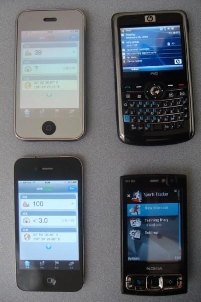
Figure 1b. Mobile phones used in the tests (from left to right, top to bottom: iPhone 3GS, HP iPaq 914c, iPhone 4, and N95)
Static Test Results
Six test positions with known coordinates were selected around the University of New South Wales (UNSW) campus. Fig. 2 shows some test positions, the picture in the middle also illustrates the typical setup of the A-GPS test. A broad range of environments can be found in the campus. All six test positions are either located in urban-like environment or indoors. Table 2 gives details of the test points.
Figure 2. The test environment – from left to right, test position 1, 4 and 6 (the picture of test point 4 also shows the typical setup of the standalone HSGPS test and A-GPS test)
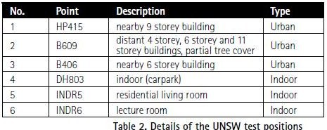
At each test position one standalone HSGPS receiver (the ublox5) was tested. 100 “cold starts” were requested by the test software, and data were logged on a laptop computer. To average out the influence on the results of the number of visible satellites and their geometric distribution, the 100 cold start tests at each test position were conducted in four groups; each group consisting of 25 tests. All four HSGPS receivers were tested in the A-GPS mode. The OSGRS was used to provide the assistance messages. There were a total of 4 times 600 location results (at 6 test positions) for the A-GPS tests.
Table 3 summarises the test results. The ublox EVK-5H receiver was chosen for the standalone test as it performs the best among the four HSGPS receivers available. In fact its performance is very good under the difficult environments. The average TTFF was as short as 36.5s and the average number of satellites used for positioning is 5. The horizontal and vertical errors are 23.3m and 29.5m respectively. The failure rate is only 23%. Test failure is defined in two ways:
• Failed test type I: A test where the receiver failed to report the position within the predefined time interval (60s)
• Failed test type II: A test where the provided position is grossly in error (the criterion is horizontal distance error greater than 550m)
When assistance was provided, the ublox EVK-5H receiver performed better. The average TTFF decreased to about 2016s and the average number of satellites increased to 6.2. The positioning accuracy was about the same, while the failure rate drops significantly to 9%. The performances of the other HSGPS receivers vary. For example, the SiRF GSCI-5000 performed the best in terms of TTFF – only 11.8s on average; however the average positioning accuracy was the worst. This suggests that there is a trade-off in receiver design between signal sensitivity and positioning accuracy [22].
–~~~~~~~~~~~~–
Kinematic Test Results
Tests of the HSGPS receiver
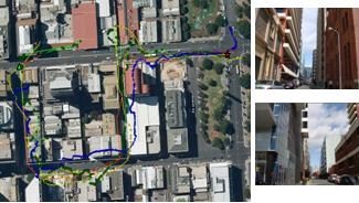
A car equipped with the four HSGPS receivers (see picture on the right upper corner of Fig. 3, antennas installed on the car roof) was driven around the Sydney CBD. Fig. 3 displays the tracks reported by the receivers (plotted on Google Earth). The two pictures on the right side show the test environment – high rise buildings block most of the sky. Under this harsh signal environment, HSGPS receivers could still provide reasonable solutions. The shape of the track is correct. The largest offset error is at the left upper corner where all the receivers report position with errors of over 100 metres – possibly caused by severe multipath. The average number of used satellites were 6.5 (ublox5), 6.5 (ublox4), 5.2 (SiRF) and 5.6 (Navman). Note that ublox also utilises SBAS (Satellite Based Augmentation System). In this test, two MTSAT (PRN 129 and 137) were tracked and used (if possible) in position calculations. This may explain the better performance of these two ublox receivers.
Tests of mobile phones
The tests of mobile phones were carried out for three scenarios: urban canyon, shopping centre, and an area under dense tree foliage. Four handsets were held by two persons walking along the same paths. The software “EasyTrails” was used on the iPhone 3GS and iPhone 4 for the tests; “Sports Tracker” from the Nokia Ovi Store was used on the N95, and a small application was developed for Windows Mobile, the HP iPaq device.
Figure 3. Kinematic test of HSGPS receivers (Navman – yellow circle; SiRF – green triangle; ublox 4 – red cross; ublox 5 – blue square; real ground track – white; start point – red star; end point – green triangle)
Fig. 4 displays the tracks obtained in the urban canyon test environment. Comparing with the kinematic test of the HSGSP receivers, this test environment is less harsh. The performances of the mobile phones were not bad – the maximum offset of the tracks reported by the handsets was about 50 metres. The effects of multipath disturbance were also evident.
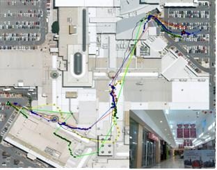
Fig. 5 shows the tracks reported by the mobile phones in the shopping centre test. It can be seen that at some areas in the shopping centre the mobile phones could report positions. The synthetic glass roof above those areas allowed satellite signals to pass through. The HSGPS chipsets could utilise the signals to calculate a PVT result. In the area covered by a concrete roof, all satellite signals were blocked, or attenuated too much, and the mobile phones could no longer provide a PVT solution. Although the accuracy of the positioning results were in general not very good, it was impressive to see the mobile phones actually working within a shopping centre environment. The iPhone 4 performed best in this test.
Figure 4. Kinematic test results of HSGPS receivers in an urban canyon environment (iPhone 3GS – red cross; iPhone 4 – yellow diamond; iPaq 914c – blue dot; N95 – green square; real ground track – white; start point – red star; end point – green triangle)
Figure 5. Kinematic test results of mobile phones in a shopping centre (symbols are the same as in Fig. 4, except real ground track – white); the right bottom corner shows the interior test environment
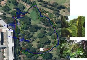
Fig. 6 displays the results of the test scenario under tree foliage. In general this scenario was less challenging than the other two. The green track generated by the N95 is close to the real ground track. Other handsets also performed well, with the exception at some places. As in previous tests, the iPhone 3GS provided sparse PVT solutions. The positioning result from the iPaq was quite variable, while that from the iPhone 4 exhibits an offset (of about 20 metres) at the beginning of the test which may be caused by multipath from a nearby multistory building.
Figure 6. Kinematic test results of mobile phones in a forested area (symbols are the same as in Fig. 4, however there is no real ground track to provide “groundtruth”)
Conclusions
HSGPS receivers are widely used for many mass market applications. Under harsh signal environments, the HSGPS receivers can still provide PVT solutions, although the accuracy is not as good as in clear sky conditions. From the tests, one can observe that, in general, the newer receivers performed best. The performance of the receivers from different the manufacturers varies – one receiver may perform very well in one aspect, but not that as well against other criteria. There is no single clear “winner” on the HSGPS receiver market. However, with technological advances a better HSGPS receiver can always be expected to be released.
References
[1] Parkinson, B.W., Spilker, J.J. (eds): Global Positioning System: Theory and Applications, Volume I, American Institute of Aeronautics and Astronautics, Inc. Washington (1996).
[2] Li, B., Mumford, P., Dempster, A.G., Rizos, C.: Secure User Plan Location (SUPL): Concept and Performance, GPS Solutions, 14(2) (2010) 153-163.
[3] GPS Wing Space & Missiles Center: Navstar Global Positioning System Interface Specification, IS-GPS-200, Revision E (2010), www.gps.gov/technical/icwg/IS-GPS-200E.pdf.
[4] SigNav: uTevo Timing Micro Module User Guide (2009), www.signav.com.au/files/brochures/uTevo-0000-User%20Guide-v0.4.pdf.
[5] Lachapelle, G., Kuusniemi, H., Dao, D., MacGougan, G., Cannon, M.E.: HSGPS Signal Analysis and Performance Under Various Indoor Conditions. Navigation, journal of the U.S. Institute of Navigation, 51(1) (2004), 29-43.
[6] Schwieger, V.: High-Sensitivity GPS — the Low Cost Future of GNSS. International Federation of Surveyors Working Week Copenhagen, Denmark (2007), p. 15.
[7] Ublox: LEA-5 ublox 5 GPS Modules Data Sheet (2009)
http://www.ublox.com/images/downloads/Product_Docs/LEA-5x_Data_Sheet%28GPS.G5-MS5-07026%29.pdf.
[8] ublox: ANTARIS Positioning Engine Protocol Specification (2003), available at http://www.u-blox.com.
[9] SiRF Technology: SiRF Binary Protocol Reference Manual, Revision 1.7. (2005).
[10] LaMance, J., Jarvinen, J., DeSalas, J.: Assisted GPS: A Low-Infrastructure Approach. GPS World, March issue (2002).
[11] Li, B., Zhang, J., Dempster, A.G., Rizos, C.: Open Source GNSS Reference Server for Assisted Global Navigation Satellite Systems, in press Journal of Navigation (2010)
[12] ublox : ANTARIS® 4 GPS Modules (2003), http://www.alphamicro.net/resources/u-blox/LEA-4x_Data_Sheet (GPS.G4-MS4-06143).pdf.
[13] Navman: Jupiter 32 Data Sheet (2007).
[14] SiRF Technology: GSCi-5000 Aided Evaluation Kit User Guide (2007).
[15] Infineon: Hammerhead II PMB2525 product brief (2006) http://www.infineon.com/cms/en/product/channel.html?channel=ff80808112ab681d0112ab6ad4ef0641&tab=2.
[16] Qualcomm: MSM6280™ Mobile Station Modem™ Device Specification (Advance Information) 80-V6968-1 Rev. C (2005).
[17] Broadcom: BCM4750UBG Single-Chip AGPS Solution (2010) http://www.broadcom.com/products/GPS/GPS-Silicon-Solutions/BCM4750.
[18] Texas Instruments: GPS5300 NaviLink™ 4.0 single-chip solution (2010), http://focus.ti.com/general/docs/wtbu/wtbuproductcontent.tsp?templateId=6123&navigationId=12607&contentId=4663.
[19] ublox: ANTARIS Positioning Engine Protocol Specification (2003), available at http://www.u-blox.com.
[20] ublox: ublox 5 NMEA, UBX Protocol, GPS.G5-X-07036-P1 (2007), available at http://www.u-blox.com.
[21] SiRF Technology: Instant GPS IC Interface Control Drawing (2007).
[22] Wieser, A.: High-sensitivity GNSS: the Trade-off Between Availability and Accuracy. Proceedings of the 3rd Symposium on Geodesy for Geotech. & Struct. Engineering / 12th Symposium on Deformation Measurements, Baden, Austria, 22-24 May (2006).
My Coordinates |
EDITORIAL |
|
His Coordinates |
Vice Admiral B R Rao |
|
Mark your calendar |
MARCH 2011 TO AUGUST 2011 |
|
News |
INDUSTRY | LBS | GPS | GIS | REMOTE SENSING | GALILEO UPDATE |
Pages: 1 2







 (22 votes, average: 1.91 out of 5)


Nice research!!!
Leave your response!