| Surveying | |
Real time monitoring of Dalian Beida Bridge
|
Wang Jun, Yi Xiaodong, Wei Erhu
|
||||
|
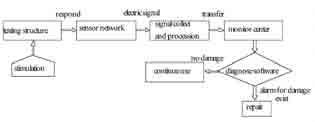
There are many traditional surveying methods used for the large-scale bridge structure deformation monitor such as the accelerometer measure, the total station surveying and the laser collimation, but these methods are limited by its function of which the continuity, timeliness and automaticity can not meet the need of the large-scale construction dynamic monitor. In recent years, with the GPS hardware and software technology developed, especially the GPS receiver with the high data-collection frequency (for example 10Hz even 20Hz[1][4]) appearanced as well as the GPS data processing was improvement, the GPS-RTK technology applied in large-scale bridge dynamic deformition monitor with real-time or quasi-realtime has become true[2][3]. Further, with the Fourier transformation tool the bridge base frequency could be obtained, the data of bridge vibrational state in spatial frame and frequency range distributed characteristic may provide the key to understand whether the bridge structure is health under the load drive environment. Structure health monitor flowchart [7] is shown in fig 1. Fig 1 Health monitor flowchart Fig 2 monitor points distribution Testing plan and processInstallment of GPS sensor antanaIn the bridge structure health examination, the sensor type, quantity and the structure testing position will guarantee the monitor effective implementation. Unsuitable sensor disposition would affect the precision of recognition parameter, one good sensor disposition plan aims to achieve: Testing process with GPS-RTKThe entire test had been implemented by TRIMBLE-5700 of the dual-frequency GPS receiver, S0, the GPS base station, located in spacious place nearby the bridge as seen in Fig 3 (a) where the error of multipath effect should be weaken, and rover station placed at s1, s2, s3, n1, n2, n3 separately, its main error source is the receiver system noise. The GPS receiver data sampling frequency was set 10HZ during testing process and data gathering time in each testing point will sustain more than 1h. Spatial distribution of dynamic deformation for bridge structureGenerally, with the external force (such as typhoon, earthquake and heavey-load car), the large-scale bridge vibration takes on simple harmonics nature, and its amplitude and frequency are changed too when the external force are changed, therefore, two kind of situations exists in the bridge dynamic deformation characteristic distribution . Where, A is an amplitude; f is a frequency; y is the deformation quantity; φ0 is the beginning phase; t is the time. Where, α is the coefficient of attenuation; Because along the direction of x and y axial, bridge vibration are smaller than that of z axial, therefore the structure vibration time interval curve obtained through computation is along the z axis. |
||||
Pages: 1 2


 (No Ratings Yet)


