| Navigation | |
Integration of Short Range Measurements into a standard Inland ECDIS navigation display
The paper describes the integration of the computed distances (called Short Range Measurements) between a barge convoy hull or passenger vessel hull and the surrounding riverside infrastructure, into a standard Inland Electronic Chart Display and Information System (ECDIS) |
 |
|
 |
|
 |
|
Approaching river locks, passing under bridges, and approaching riverside berths and ports were identified as the situations at inland waterway transportation with the highest risk with respect to the collisions with surrounding infrastructure [1]. The first one is the most difficult because of the obstructions on both sides and sometimes the lock width is only one meter wider than the hull of the convoy. A convoy can be composed of a certain number of (un-motorised) barges which are pushed by a cargo vessel or a push boat. Passing under the bridge is not easy since the convoy has to pass a narrow corridor (between bridge pylons) at normal cruising speed and may cause problems especially during bad weather conditions, e.g., rain, fog, etc., when no clear view to the bridge is possible.
In order to support the skipper to take the right navigation decisions when he faces these three scenarios, a system was designed, within the NAVWAT 2 project [1], [2]. It provides accurate and reliable navigation information in a kind of visual guidance system. Based on the information about the river infrastructure and the convoy itself, short ranges between them are measured and shown. Thus, the skipper has a better overview of the whole situation, and by knowing these ranges, he can perform correct manoeuvres in order to avoid any collisions or accidents.
Inland ECDIS viewer software displays Inland Electronic Navigational Charts (Inland ENCs) to visualize the surrounding infrastructure, other convoys currently sailing and other important information for inland waterway navigation. One of the services which are not available at Inland ECDIS viewer software is measuring the distances to surrounding river infrastructure and thus, this was the main goal of the NAWVAT 2 project. Therefore, an integration of Short Range Measurements (SRM) into Inland ECDIS was realized. The research work and the integration which are described in this paper are conducted within the ‘Implementation of River Information Services in Europe 3 (IRIS Europe 3)’ project [3].
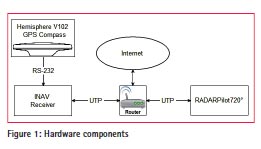
Hardware components
Figure 1 shows the devices and connections of the overall integration of the system. The system developed in the NAWVAT 2 project is located in the so-called INAV receiver. It uses raw data, heading and Rate-Of-Turn (ROT), sent by the Hemisphere heading device to generate navigational data, i.e., position, velocity, time, integrity, etc. The INAV receiver runs on a Linux Operating System and provides different interfaces such as Ethernet, UART, USB and four status LEDs. The SRM computed by the INAV receiver are sent to the Inland ECDIS navigation system (RADARPilot720° [4]) through a router. The router also provides possibilities to external services which can be used by both devices.
Software implementation of INAV receiver
The software consists of two parts. The first one generates the navigational data and the second one uses this data in combination with the riverside infrastructure to compute the short ranges.
Position estimation
The Position, Velocity and Time (PVT) software of the INAV receiver is responsible for computing the navigation solution and the predicted convoy track, and provides them to the SRM module. The PVT collects all necessary data from the Hemisphere GPS compass – raw measurements (pseudoranges, phases, Doppler measurements and carrier-to-noise ratios) and ephemeris information for all GPS satellites in view, heading information (roll, pitch and heave), ROT and course over ground (COG). The heading information and ROT are not processed within the PVT, but they are passed to the SRM module.
The PVT uses GPS measurements and ephemeris to continuously compute the convoy position, velocity and COG. Raw measurements are analyzed for anomalies, outliers which can be removed accordingly. The position estimation is based on a Kalman filter with automatic selection of appropriate models for convoy dynamics (static, kinematic). The PVT includes a RAIM algorithm which is able to detect the erroneous data from satellites.
The PVT also computes the integrity information – vertical (VPL) and horizontal protection level (HPL). The HPL is used to proof the necessary integrity and reliability of positioning.
The predicted track is computed using actual position, velocity and ROT. The PVT computes the predicted track and the corresponding COG with a regular interval. The length of the predicted track can be changed, however reasonable values are in the range of 30-50 seconds.
In order to increase the positioning accuracy, the PVT can utilize DGPS corrections in RTCM 2.3 format. The INAV receiver has an embedded NTRIP client which is able to communicate with a correction broadcaster [5]. DGPS corrections can be received via Internet or directly from the RADARPilot720°.
SRM module
This module contains the most important functions and algorithms for SRM. It is also responsible for communication with the RADARPilot720° and visualising the SRM on its viewer. The SRM module receives navigational data as NMEA sentences from the PVT software (each epoch). The important parameters, i.e., position, velocity, heading, ROT, COG, etc., are extracted out of these NMEA sentences and are used for determining the position, orientation, moving direction, etc., of the whole convoy.
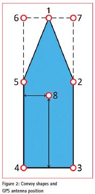
Two connections (A1 and A2) are established between the SRM module and RADARPilot720°. A1 is a unidirectional connection where all available NMEA sentences are forwarded as a data stream to the RADARPilot720°. Whereas A2, a bidirectional one, uses the Simple Object Access Protocol (SOAP) and is used for SRM computation. The first information sent through A2 are the data about the convoy shape, i.e., its length and width, position of GPS antenna mounted on the convoy and all vertices of the convoy real shape with respect to its body reference frame. These data are mandatory and without receiving them correctly, no further computation can be performed. Using the real shape, a reference one is created, which actually is a kind of best-fitting envelope. In Figure 2, the polygon consisting of vertices 1, 2, 3, 4, 5 and again 1, represents the real shape, whereas the reference shape is a quadrangular polygon created by the most external vertices of the real one, i.e., the vertices: 6, 7, 3, and 4. Therefore, the width and length of the convoy are represented by distances between vertices 4 and 3, and 4 and 6 respectively. The vertex 8 represents the position of the GPS antenna.
All distances will be determined between the reference shape and the riverside infrastructure. This convoy information is received by the SRM module at anytime the skipper modifies the real shape or changes the position of the antenna.
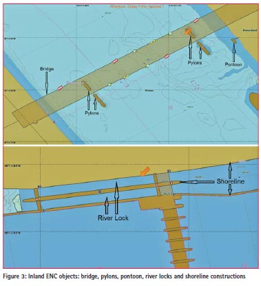
After the first correct position of the convoy is estimated and forwarded to the RADARPilot720°, it gathers from its Inland ENC all available river infrastructure elements (so called Inland ENC objects) detected within a circle with a predefined radius (e.g. 1 km) and sends them through A2 to the SRM module. Each time the convoy exceeds this circle, the RADARPilot720° searches for new Inland ENC objects and sends them again to the SRM module. There are two most important parameters for each Inland ENC object, i.e., Object Class (e.g., bridge, bridge pylon, lock basin, shoreline construction or pontoon) and the register of WGS84 coordinates of all vertices that form the real contour of that element. Now, knowing the current position of the convoy and the river infrastructure around it, SRM module searches for the closest Inland ENC object and measures the distances to it. The SRM module computes distances only when the convoy gets closer to the Inland ENC object than a predefined threshold, e.g., 200 meters. Since Inland ENC objects have different type of geometry, i.e., point, line, polyline, polygon, etc., and only their geometry is provided through their vertices, it was challenging to develop a common algorithm which extracts the correct points out of this geometry to measure the distances. If the convoy is inside the Inland ENC object, e.g., inside a river lock, the short ranges will be measured directly to the object geometry, and if it is close to the riverside infrastructure distances will be measured to the predefined approach reference lines. No matter the geometry, position and orientation of the Inland ENC objects, moving direction and orientation of the convoy (forward or backward, i.e., when convoy gets closer to the object with its rear side), the SRM module is able to measure the distances – to bridges with no pylons at all and bridges with one or more pylons, to pylons which do not belong to any bridge (bridge was removed), to shoreline constructions, river locks and pontoons, see Figure 3. The short ranges are measured between projected points of the convoy reference shape onto the Inland ENC object geometry and/ or onto the approach reference lines.
For each epoch, the SRM module sends this information to the RADARPilot720° through A2:
1. Convoy reference shape, and
2. Predicted track
If the convoy is close to any Inland ENC object, it computes the distances and sends this information also:
1. Approach reference lines (if predefined),
2. Distance values in meters, and
3. Warning messages
During normal operation mode, the reference shape, predicted track and the lines of distances are visualised in green colour. If the integrity of the position solution is not given, the skipper is informed through a warning message on the RADARPilot720° screen and colours change to red. Another warning message is shown to the skipper when the convoy is too close to an object and could collide accordingly.
Another message sent by the RADARPilot720° through A2 is the shutting down message to inform the INAV receiver to automatically shut down on its own because the whole system will be turned off.
Tests and results
A real-time testing campaign was organized in September 2014 on the Danube River in three countries, in Hungary (from river km. ~1639 to ~1660), Austria (from river km ~1998 to ~2040) and Romania (from river km ~785 to ~805). Depending on the availability and quality of the Inland ENC objects in each testing area, different test cases were carried out.
The overall position estimation, reception and use of GNSS corrections, the overall computing procedures as well as accuracy of SRM, integrity and usability tests were carried out within this campaign.
Static tests were performed by installing Hemisphere device at a point with known coordinates. The NMEA data and some statistical information (e.g., correlation matrix) from the INAV receiver were collected during 8 hours. The Root Mean Square (RMS) error for this case (Kalman filter with dynamic model for static case) is 1.5 m. The sigma values estimated by PVT were consistent with computed RMS error.
The errors (for plane coordinates) computed by the PVT in kinematic mode (at moving convoy) were 1.8-2.5 m. Solution quality in vicinity of bridges is normally worse than normal due to satellite signal shading caused by the bridge and receiving reflected signals from metallic constructions. Such anomalies are very well detected by the integrity algorithm and an alarm message is displayed on the RADARPilot720°. Tests showed that a selected priori alert limit of 2 m is reasonable for the application.
In Austria, DGPS corrections were available. The INAV receiver obtained corrections using an internet connection. The correction information was sent every second (RTCMmessage 1) and information about reference station position was sent every 20 seconds (RTCM-message 3). The device switched automatically to stand-alone solution if the correction reception is interrupted due to any reason (solution types are indicated by status LEDs). The DGPS corrections reduced the RMS error to about 1 m.
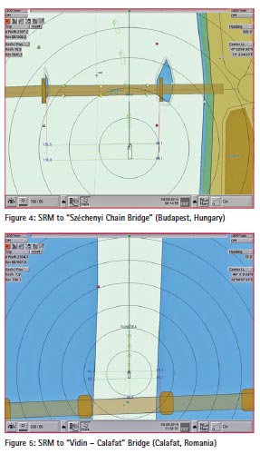
Figure 4 shows a screenshot of the RADARPilot720° visualising the computed distances. The distances are measured to the nearest Inland ENC object, in the present case to the Széchenyi Chain Bridge which has two pylons. The black pentagon is the convoy’s real shape and the green envelope represents the reference one. The GPS antenna mounted on the convoy is marked with a blue cross. At both sides of the convoy, the approach reference lines (the red ones) are displayed which are predefined virtual lines based on the geometry of the pylons. As soon as the convoy gets closer to the bridge, the approach reference lines get shorter. The thin green lines connect the vertices of the reference shape with their projected points on the bridge and on both approach reference lines. Whereas, the values placed on the projected points show the distances in meters. The predicted track of the convoy is also provided in Figure 4. The small green circles represent the predicted positions of the GPS antenna and the green pentagons are the predicted positions of the real shape. The following Figure 5 shows a screenshot after the convoy passed under the bridge. It shows the same information as Figure 4 except the distance to the bridge now is measured from the rear side of the convoy.
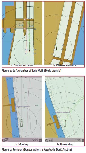
In case of approaching a lock, the SRM module provides accurate distance information visualized on the Inland ECDIS display. Figure 6a, shows the convoy getting closer to the lock from its eastern side. At the right side of the convoy, the distances are measured to the shoreline construction and for the left side an approach reference line to the lock chamber is used. Also, the distance to the eastern entrance is shown. As soon as the convoy is inside the lock (Figure 6b), the distances are measured to the geometry of the lock itself. A screenshot during a mooring manoeuvre to a pontoon is shown in Figure 7a. Since the convoy did not reach the pontoon, an approach reference line is used again to provide the skipper the relevant distance information. A threshold is used for the predicted track, i.e., if the convoy velocity is smaller than this threshold, the predicted track is the same as the current position (Figure 7a). When the convoy gets closer to the pontoon, the distances are measured directly to the pontoon object (without approaching line), Figure 7b.
The computed distances were compared with distances measured by laser distance meter unit (Leica DISTOTM D110) in real-time and the differences between them were in decimetre-level. Skippers and the participants at the test campaign evaluated this service (SRM) as very practical, useful and helpful. They also reviewed the performance of the INAV receiver as very satisfactory.
Two problems with higher influence in SRM accuracy were detected during the tests: Loss of satellite tracking under bridges for a short time and the inaccuracy of the Inland ENCs. Very precise measurements of river infrastructure are required.
Reports and video record files about the test campaign will be published on the IRIS Europe 3 project webpage [3].
Conclusion
Despite the development and modernization of the waterway sector in the last years, some different scenarios still provide high risk with respect to collisions with surrounding infrastructure. In this paper, the integration of an additional service (SRM) to the Inland ECDIS navigation display is presented in order to support the skippers with real-time information about passing and docking manoeuvres, and to help them in avoiding any collisions with the riverside infrastructure.
The accuracy of the PVT solution in kinematic and static cases is reasonable. However, in case of approaching bridges, the GPS error increases due to satellite signal shading. In most cases, the receiver loses the satellite signals for about 2-3 seconds. In order to mitigate these problems, additional measurements from inertial sensors available on the GPS compass maybe used. Furthermore, the predicted track algorithm can also overcome the problem. Finally, it is worth to mention that the short signal outages are not a real problem since the overall system is supporting the approach to a bridge and thus, the functionality is not negatively influenced.
Differential corrections improve the position accuracy. It was demonstrated that the connection between the broadcaster and PVT via mobile Internet was stable and fast enough to receive correction information every second.
The SRM module uses the navigational data generated by the PVT software and the Inland ENCs to measure the distances between the convoy reference shape and the Inland ENC objects. The amount of information about the Inland ENC objects provided to SRM module is enough to compute the distances, but with more detailed information about them (knowing if Inland ENC object or part of it is above the water or on ground, waterways, notice marks, etc.,) the performances of the SRM module and the overall INAV receiver can be increased.
References
[1] NAVWAT 2: http://www.navwat.at/
[2] Report about test in Vienna: http:// www.via-donau.org/newsroom/ aktuelles/news detailansicht/nid/1514/
[3] IRIS Europe: http://www. iris-europe.net/
[4] Manufacturer’s webpage: http:// www.innovative-navigation.de/
[5] RTCM (2004b) RTCM Recommended Standards for Network Transport of RTCM via Internet Protocol (NTRIP), Version 1.0, RTCM Paper 200-2004/SC104-STD


 (3 votes, average: 2.33 out of 5)


Leave your response!