| GNSS | |
GNSS Vulnerabilities at sea
The paper examines how jamming impacts GNSS receiver function and performance, and quantifies that impact particularly for operational use by SOLAS (Safety of Life at Sea) marine users |
 |
|
 |
|
|
|
|
 |
|
 |
|
 |
|
 |
|
 |
|
 |
|
Applications and services based upon GNSS are becoming increasingly embedded in modern society, to the extent that we Europeans, along with much of the rest of the World, have now become critically dependent upon their correct operation. In the event of GNSS problems, telecommunications networks could fail, aeroplanes and ships could stray off course, power grids could become unstable, financial transactions could become unreliable, the whole world of logistics could crumble, and train doors could fail to open in stations to let passengers on or off. These and many more applications and services presently take advantage of a unique conjunction of beneficial elements, in some cases without even realising that GNSS lies at their heart:
• GNSS services are for the most part free of charge at the point of use;
• GNSS equipment is astonishingly cheap;
• GNSS performance is outstandingly accurate, and reliable, and it is available ubiquitously to all of humanity irrespective of race, colour or creed.
This combination makes GNSS dependency inevitable, and in many respects highly desirable in advanced modern society. And yet threats and vulnerabilities exist that are neither addressed, nor even understood by the overwhelming majority of those who depend on GNSS for the successful accomplishment of their daily lives.
This paper is based on a presentation [ix] given to the ENC Conference in Vienna in April 2013. It reports from the STAVOG study that examined two major threats and vulnerabilities of GNSS, namely jamming and severe ionospheric disturbance. In this paper due to space constraints we report only on the jamming analyses. We examine how jamming impacts GNSS receiver function and performance, and quantifies that impact particularly for operational use by SOLAS (Safety of Life at Sea) marine users.
User domains impacted by GNSS T&V
A wide set of GNSS User Domains were analysed and categorized by the level of impact on their operations of threats and vulnerabilities of GNSS. The needs were assessed based on the impact potentially caused by loss of GNSS services, or by erroneous navigation data. Such impacts included safety, financial, and environmental. A total of 21 distinct application domains were identified as heavily impacted. These included:
• Maritime, particularly SOLAS-related;
• Aviation, particularly Integrity-dependent;
• High-value services including navigation and timing dependencies.
Standards were identified as very important to a number of the user domains. Current standards pertaining to GNSS vulnerabilities and needs for robustness were assessed as at best weak, and at worst absent. Although certain initiatives were identified (for example GLAs efforts to address GNSS vulnerabilities for the maritime domain), these appear to be the minority, with most application domains apparently ignorant about such vulnerabilities.
Many user domains appear to place a higher level of reliance on RAIM-type algorithms in GNSS receivers than the authors consider is safe. RAIM algorithms have evolved over many years to be good at detecting the types of faults they were designed to cope with, typically step changes or ramps in pseudorange errors from one or several satellites. The errors caused by interference do not generally fit the error characteristics that RAIM algorithms were designed for, and consequently it is unsurprising that the performance of receivers with RAIM was found to be unacceptable in the presence of interference, as is reported in this paper. This important finding is highlighted since it appears to have escaped the attention of many.
Maritime User Requirements
Marine SOLAS was selected as a specific user domain to study in detail. The marine SOLAS GNSS receivers, whether (D) GPS and/or (D)GLONASS are subject to existing IMO performance standards (listed below). Each performance standard is itself the subject of a corresponding IEC test specification (the IEC61108 range) which defines what tests are required to prove the IMO performance standard. In addition there are several other generic standards that list performance requirements (also listed below). Therefore all existing receivers are subject to meeting the following standards.
• GPS receivers should perform in accordance with IMO Resolution MSC.112 (73) (2000)
• DGPS receivers should perform in accordance with IMO Resolution MSC.114(73) (2000)
• The IEC 61108-X test series refer to GNSS and DGNSS receivers.
• Such equipment should perform in accordance to the general requirements contained in IMO resolution A.694(17)
• Such equipment should perform in accordance to IEC 60945
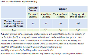
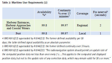
In order to implement specific measureable performance, a single specific maritime application was selected, albeit one of wide utility. This is that of “Harbour Entrances, Harbour Approaches and Coastal Waters”. Many aspects of the specification may be applicable to other applications but any such use is advised to take careful note of the particular focus and to take responsibility for any difference between their use and the particular application in this specification. Work undertaken by the International Maritime Organisation (IMO [i], u pdated as noted by a later IMO document [ii]), provides a number of general requirements as well as specific performance demands. Among these, requirements related to “Harbour Entrances, Harbour Approaches and Coastal Waters” can be extracted, and are provided below:
§ 2.1.1.3: …”GPS has been recognized as a component of the World Wide Radionavigation System (WWRNS) for navigational use in waters ….”
§ 2.1.1.4: … “GPS does not provide instantaneous warning of system malfunction. However, differential corrections can enhance accuracy (in limited geographic areas) to 10 m or less (95%) and also offer external integrity monitoring. Internal integrity provision is possible by autonomous integrity monitoring using redundant observations from either GNSS or other (radio) navigation systems, or both”.
IMO also discuss GLONASS in a subsequent section; this is treated essentially the same as GPS as a component of WWRNS.
Appendices 2 and 3 of the IMO document provide tables of minimum maritime user requirements for navigation and positioning. Appendix 2 applies to “general navigation”. Appendix 3 applies to “positioning” and includes several Tables: Table 1 “Manoeuvring and traffic management applications”; Table 2 “Search and rescue, hydrography, oceanography, marine engineering, construction, maintenance and management and aids to navigation management”; Table 3 “Port operations, casualty analysis, and offshore exploration and exploitation”; Table 4 “Fisheries, recreation and leisure applications”. Relevant sections from the IMO Requirements pertinent to “Harbour Entrances, Harbour Approaches and Coastal Waters” are provided here for information. Although great care has been taken with this, in the event of discrepancy between the present work and IMO, the IMO originals should be used, taking careful note that the IMO specification A915(22) was qualified in parts by a later document IMO in A1046(27).
Potential future requirements for robust navigation in maritime domain
A number of desirable Marine Community potential future requirements were defined by the project team. These are not presently standardised, but are presented here as an outline set for consideration and comment by the wider community. These were used as part of the analysis of performance reported below.
The GNSS receiver should:
1. Mitigate the problem if at all possible – provide continuous, resilient PNT.
2. Identify that there is a problem as soon as possible after it occurs.
3. Continue to operate with ‘graceful degradation’ of performance with a limited amount of jamming for a particular roll over time – the time is dependent on application and the amount of jamming present.
4. Raise an alert when the reported position changes beyond the realistic dynamics of the vessel.
5. No false or misleading information presented to the mariner.
6. Stop providing a position and alert that there is a problem when jamming gets too much.
7. When jamming ceases, receivers should recover within 1 minute, in line with a warm start requirement.
Based on the fact the current standards do not include any of these items, there remains a strong suspicion that current operational equipment in some, and potentially many, domains may not be adequately capable of coping with interference or ionospheric scintillation problems.
Specification of interference/jamming
Two distinct categories of jammers were considered in Project STAVOG. The first type, PPDs (or Personal Protection Devices), are small jammers which all use a comparatively low transmission power. As a product (albeit an illegal one) they are aimed to disrupt / block GNSS signal reception in the immediate vicinity of the jammer, typically within 5 metres or so, although some have sufficient power to block signal reception at substantially longer ranges, and degrade signal reception over a wider area still.
The second type of jammers considered were higher-power jammers, designed to disrupt / block GNSS signal reception at a distance of up to tens of kilometres. Other sources of GNSS interference may be accidental but often behave like either PPDs or higher-power jammers depending on the power and characteristics of transmissions into the GNSS bands.
A number of researchers have published characteristics of small PPD-type jammers that, although illegal to operate, are available for sale on the internet and are known to be used for a variety of purposes including:
• Disabling vehicle tracking devices;
• Avoiding GNSS-based tolls;
• Blocking tracking devices.
Although STAVOG project did not focus on protecting any of those applications, other GNSS-based applications including the maritime community, other safety of life users, and critical infrastructure users can be “accidentally” impacted by nearby PPDs.
The analysed publications are in some cases quite thorough in defining detailed jammer characteristics (as illustrated by Figure 1 and Figure 2) such as centre frequency, bandwidth, temporal, power and other characteristics of jammers found. Such information is invaluable to the community in assessing the threats with which it must cope, and this information was used as the basis for the STAVOG definitions of PPD jammers.
In the public domain, information published about larger, higher powered jammers was found to be quite sparse. The specifications for such units used in project STAVOG were therefore based on a combination of well-known jamming models and higher-powered versions of PPD characteristics.
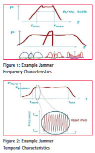
Several research groups have analysed PPD jammer characteristics, providing an invaluable input to threat assessments and performance analyses such as those undertaken in project STAVOG. Kraus et al [iii] analysed seven PPD units and provided their technical characteristics in substantial detail. He reported peak powers up to 0.11mW, although most jammers were an order of magnitude weaker. Mitch et al [iv] characterised signal properties of 18 commercially available GPS jammers (PPDs). Mitch found that all jammers used a swept tone, and reported powers up to 23mW and even 640mW, substantially higher powers than had been found by Kraus. Both Mitch and Kraus found that the majority used chirplike signals. Tong [v] reported analyses of PPDs, but provided a presentation rather than a full technical report, consequently and regrettably providing less detail than some other researchers. Guinand et al [vi] undertook various works including laboratory characterisation of jammers; he found chirp jammers but also noted other characteristics in some units. Like Mitch, Guinard reported jamming powers of PPDs up to hundreds of mW. Most jammers attack the GPS L1 frequency (1575.42 MHz), but some implement multiple frequencies. Sweep rates of microseconds to tens of microseconds appear most common. Borio et al [x] also recently characterised jammers. Although their work was not available in time to consider for implementation in the project STAVOG, it is noted that the jammers they found and analysed were nevertheless consistent with those modelled for STAVOG.
The twin fears for User Communities with all forms of jamming and interference are:
a) That a GNSS receiver is unable to maintain tracking lock on the satellite measurements, potentially leading to a navigation outage.
b) That a GNSS receiver’s measurement ability is degraded to the extent that it is still able to maintain lock on the satellite measurements, and thereby produce a navigation fix, but that the measurement accuracy may be degraded to the extent that the measurements lead to the derivation of erroneous position fixes (i.e. position fixes outside of acceptable tolerance). Associated with this type of degradation is the additional risk that the receiver may not autonomously determine that its position solution is degraded, thereby potentially leading to the delivery of Hazardously Misleading Information (HMI).
User Scenarios
Characterising the jamming threat alone is insufficient to understand the impact on User Communities of jamming. Operationally, the impact of a jammer close to a user will generally be much more severe than the impact of a distant jammer. If Users in a particular domain never approach a jamming source closely, then even widespread use of jammers may have negligible operational impact on operations in that domain. Within Project STAVOG, operational proximity to sources of jamming / interference were characterised through User Scenarios. These Scenarios simultaneously served two major aims:
a) explain to users in terminology, and in physical terms with which they were familiar, the exposure that their operations risk with respect to jamming and to ionospheric scintillations; and
b) to quantify the user operational exposure to threats in terms that could subsequently be simulated using the available state-ofthe art-simulation tools.
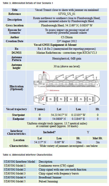
Two categories of User Jamming Scenario were created for the selected maritime SOLAS users. The first was of a shore-based jammer / interferer; the second of a jammer onboard a vessel. Abbreviated details from the first scenario details are provided in Table 3.
A wide variety of interferers / jammers were modelled during the project. The frequency and temporal characteristics are relatively complex and will not be covered in this short paper but were based on the characteristics from a number of researchers as cited in section V above. Table 4 presents an abbreviated description of the main different categories of interferer modelled. These are based on those observed “in the wild” and published in open literature. A variety of different power levels and temporal characteristics were modelled to cover the range of reported jammers. A subset are covered in the test results presented later in this paper.
Configuration for Tests
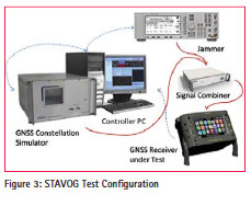
Test Facilities fundamentally comprised a state-of-the-art GNSS Constellation Simulator, a source of disturbance (interference / jamming / ionospheric scintillation), an interconnect to the receiver under test, and a control unit, as shown in Figure 3. In the figure the source of disturbance is marked “jammer” for illustrative purposes.
The state-of-the-art GNSS Constellation Simulator models satellites of the desired type (GPS, Galileo, GLONASS, etc.) and derives their motion relative to the defined user track parameters. The Simulator produces radio signals representative of those that would enter the GNSS receiver under test through its antenna port.
The source of disturbance generates interference / jamming, or ionospheric scintillation. Ionospheric scintillation is dealt with internally to the Spirent Simulator and the external unit is not required. Interference / jamming is generally dealt with as an external (RF) source, controlled by the same controller as the Simulator. The signal power from the interferer is controlled depending upon (a) the power of the jammer we wished to model, and (b) the user / jammer separation including modelling of power variations from modelled user motion. This was particularly important for Scenario 1, with the vessel moving past a jammer ashore. The signal combiner unit takes simulated GNSS signals and disturbance (interference / jamming) signals and combines them at appropriate power levels for the receiver under test. The receiver under test generally interfaces to the signal combiner via its antenna port. Different configurations may also be used, particularly for receivers with built-in antennas. The Controller PC is the control unit for the whole system and instructs the controlled equipment on simulation parameters. It may typically be fed with a data input from the receiver under test for real-time or post-processed analysis of the receiver performance.
Test Results to Scenario 1: Jammer Ashore
The scenario 1 testing required the use of a modelled Yagi antenna, the power levels were modelled to have a main high powered zone, (corresponding to the main lobe on the Yagi array), and a lower powered zone either side, (corresponding to the side lobes of the Yagi array). This type of antenna typically has a null point between the side lobes and the main high power lobe. Previous live jamming trials undertaken by the GLAs had showed the effects of this profile where there was a slight recovery in navigation as the vessel passed from the low powered to high powered zones through the null. Three jammer powers were implemented for Scenario 1: 23mW, 640mW, and 25W. A variety of jammer characteristics were implemented as previously explained (Table 4).
The scenario was created with the vessels route planned to pass by Flamborough Head on a straight course. The transmitting antenna was profiled to represent a typical Yagi antenna. The vessel would pass through a zone of no interference for approximately 13 minutes so that the receiver could receive a full navigation broadcast, then a zone of low level, a zone of higher power then a lower power zone and finally a period of no interference.
During the testing both receivers were reset each time before the scenario was run and started from a cold start state. There were complexities to this operation with certain receivers but this is not considered material for this paper. At the end of each scenario the NMEA from the receiver and the truth NMEA from the Simulator were saved along with the post process file which captured the interference levels and received interference levels along with positional information of the vessel.
The files were used to produce a plan error plot for each scenario run and a Google Earth plot of the route output by the receiver.
Power levels and free-space path loss had been pre-calculated and pretested and gave a good understanding of whether and where the interference would have an effect on the receiver in the scenario. It was expected that the lower level tests at 23mW would have a limited effect, the 640mW tests would have a larger and/or earlier effect, and the high power tests would have a definite and more prolonged effect. What was not known was the extent of the period of potential HMI before the receiver would stop navigating, nor was the period known for the receiver to recover when moving out of the high power jamming zone.
A period of high error with no alert was particularly evident with Rx 1 (anonymised as noted previously) during the CW test at 23mW and 640mW. The results showed there was a period of time where the positioning error was high prior to the point where the receiver stopped navigating, but that this did not consistently result in an alert being raised. More detail is given below.
Generally the reacquisition was seen to be a clean response with little positional error at the point navigation resumes. The exception to this was the CW test with a high power (25W) jammer where there was an initial recovery followed by some larger errors.
A visual comparison is presented in Figure 4 of the STAVOG Simulation results against previous live jamming trials conducted by the GLAs. Although precise details (jammer beamwidth and other characteristics, precise Marine Receiver used) differed, the gross characteristics of the results gave good confidence that the simulation approach was consistent with operational experience.
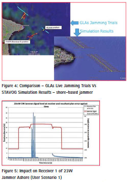
In Figure 5 results are presented from tests with Receiver 1 encountering a modest power (23mW) jammer ahore. The horizontal axis is time from start of the test. The vertical scale is (a) received signal power, dBm with the red line showing received power level against the RHS axis, and (b) horizontal error of the receiver in metres with the blue line showing error against the LHS axis.
It can be seen that as the receiver enters the first main sidelobe of the jammer, around 700 seconds into the track, there is no effect on positioning error. Once it enters the main lobe, however, at around 1550 seconds into the track, the position becomes unreliable, displaying peak errors of 45 m. Figure 6 shows further detail of this period. No alert was raised during this period. As shown in Table 1, the positioning error required is better than 10 metres (or 1 m for port operations), with an alert limit of 25 metres (or 2.5 metres for ports). This is a clear failure of a mainstream marine receiver approved under IMO and other relevant regulation for marine use. It is assumed that the receiver’s implementation of RAIM was never designed to cope with jamming or interference; its inability to reliably alert on such errors is therefore not altogether surprising. It is clear that IMO and other standards need to rapidly evolve to address this known threat.
A duplicate test was conducted but with a higher jammer power (640mW). Clearly the impact of the jamming in this test was expected to be much more severe. Results are summarised in Figure 7. In this case, with the higher jamming power, the receiver is disturbed whilst within the jammer sidelobe, and positioning becomes unreliable for about 60 seconds between 1300 and 1360 seconds (simulation time). During this period position errors of up to 25 metres were recorded (illustrated in Figure 8) with no alert sounded. As it entered the main jamming lobe, the receiver was unable to maintain track on the satellites and ceased to produce a position solution as shown. An alert was raised within approximately 14 seconds of the position solution becoming unavailable. This fails (but is not far outside) the IMO specification of 10 seconds time to alert.
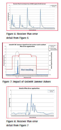
A further set of tests were repeated with the jammer power increased to 25W. In this case, the receiver behaviour was “more acceptable”, in that the jamming power swamped all signal reception as soon as the receiver entered the jammer sidelobes. Position solutions could not be produced at all during the jamming period. Once the receiver had passed right through the jammer beam and had exited the jamming sidelobe, at the point of reacquisition, a short period of very high error, peak of 460 metres, was observed and persisted above 50 m for 30 seconds as shown in the horizontal error plot (Figure 9) and the track plot of Figure 10. Although it could be argued that this post-jamming behaviour might be “expected”, for example by receiver designers, there remains a question about whether such behaviour is “acceptable”, for example to the marine community. The occurrence of large position errors without an associated alert is certainly a cause for concern, and further evidence of the inadequacy of existing approved SOLAS Marine Receiver techniques to cope with the impact of interference.
When these tests were repeated with Receiver 2 (again anonymised) the results were less “exciting”. Under 23mW and under 640mW jamming, the receiver continued to track and was apparently unaffected, although in one case with the higher powered jammer the position error did exceed 4m. When jamming power was increased to 25W, the receiver lost lock and was unable to navigate as illustrated in Figure 11. No spurious errors were observed in this instance, highlighting the difference in performance between two receivers, both fully compliant with current marine standards.
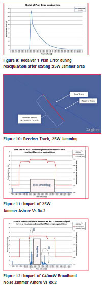
Other interference types produced broadly similar results – see for example Figure 12. Higher powers led to positioning outages; very low powers caused no effect; but medium power levels led to receivers generating potentially hazardously misleading information (HMI). The exception found from these tests was that pulsed interference caused no discernible effect. A explanation was considered, and future examination may prove whether it is correct, or whether there was some other reason for the observation: The jamming pulse implemented was very short, of only 10.7µsec “on” duration, over a pulse duty cycle of 1.5 seconds. If the receivers AGC or other pulseblanking mechanism were able to adapt rapidly enough to the changing power level, then the receiver would have had sufficient signal in the unjammed time to navigate with minimal impact on signal (and consequently positioning) quality. It is noted that pulsed PPDs have not been reported by any of the cited researchers. This may reflect their lack of effectiveness, the ease with which they can be countered, or may be coincidental.
Test Results to Scenario 2: Jammer Aboard
A second main jamming scenario was also investigated, this time simulating a jammer aboard ship. In this instance, PPD jammers were simulated, with much lower powers than implemented for Scenario 1. In this instance however, the simulation placed the jammer very close to the receiver antenna. Combinations of different separations (5, 15, and 30 metres), different power levels (from 0.001mW to 0.1mW), and different jammer characteristics led to implementation of 34 scenarios for each receiver tested.
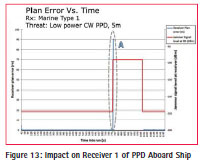
An example output is provided in Figure 13, in this case for Marine Receiver Type 1, for a CW PPD of 0.001mW power, and with 5m separation between jammer and receive antenna. The jammer was initially switched off to ensure that the receiver acquired data and position and was navigating correctly. When the jamming was switched on the receiver output position grew rapidly (spiked) to approximately 90 metres, in only 4 seconds, before the receivers positioning capability was lost. Although this short duration HMI is undesirable, position spikes are arguably fairly easy to detect by eye or by electronic means. In addition, the short duration of the position spike was less than the Alert Time mandated by IMO.
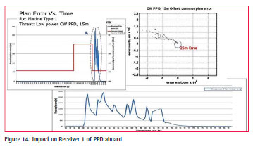
A more surprising and more extreme example is shown in Figure 14. This actually implemented the same low power PPD against the same marine receiver. In this case, however, the separation between jammer and receiver was 15m. The three figures illustrate the plan error against time (also showing jamming power), the horizontal error plot, and a zoomed in version of the plan error against time.
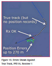
Prior to the commencement of jamming, the receiver was able to navigate successfully. When the jamming was switched on, navigation capability was lost immediately, and no position output was generated during the jammed period. These two observations are very positive since no HMI was generated. Unfortunately, once the jamming was switched off, the receiver appeared to rapidly regain tracking lock and produced position fixes of acceptable quality for 12 seconds, after which positioning went “haywire” for approximately 60 seconds. Position error excursions up to approximately 270 metres were observed, and no alert was raised. The particularly confusing thing about this finding was that the jamming source had been switched off before the erratic behaviour began. This type of behaviour is considered a serious concern for the marine community. As shown in Figure 15, where the errored position reports are shown superimposed on True Track, had such errors been used to navigate a vessel in narrow or restricted waterways, the consequence could have been very serious.
In some other experiments, particularly when jamming power was low and separation between jammer and receiver was high (30m), the receiver was able to continue navigating despite the interference. In other cases, where incident jamming power was higher, the receiver was unable to produce a position output; sometimes an alert was raised. HMI was observed in only a few of our experiments with PPDs, and no other jammer / receiver combination yielded such dramatic effects as reported above.
These results highlight, however, that marine receivers in operation today, that are fully compliant with all mandatory function and performance specifications, are unable to operate in the presence of low-cost jammers that are available and regularly observed “in the wild” today, and in some cases the results may be dangerous.
Conclusions
A number of conclusions can be drawn from the work undertaken within project STAVOG and reported here.
I. The STAVOG simulation tests were conducted against operational marine receivers that are fully compliant with IMO and other standards. A state-of-the-art Spirent Simulator was used to replicate jamming (and ionospheric scintillation) conditions.
II. The simulation approach provided a number of benefits including: it provided the benefits of repeatability, controllability, precise knowledge of the satellite and jamming signals, leading to verifiability and traceability of results; it saved expense and time compared with field trials; it caused no impact on other GNSS users; and the security of the tests (e.g. from eavesdroppers) was assured since signals were not transmitted externally.
III. The interference / jamming results showed periods of (i) blockage (jamming too severe to permit navigation), (ii) safe navigation with acceptable performance (jamming ineffective), and (iii) HMI where position errors exceeded acceptable levels but with no alarm raised.
IV. In some cases, the temporal characteristics of the HMI errors would have been easy for “gross reasonableness checks” within the receiver or associated shipborne equipment to detect. The fact that the errored solutions were in some cases delivered without warning messages implies that the tested marinegrade receivers did not utilise such “gross reasonableness checks”.
V. It was found possible for a marinegrade GNSS receiver to produce prolonged HMI (Hazardously Misleading Information) without generating an Alert message. That these units are (a) operational and in widespread use today, (b) fully compliant with maritime standards, but (c) woefully unable to cope with a variety of credible interference / jamming threats, is a serious concern.
VI. Scenario 1 (Approach to port with Interferer on mainland) identified that a High powered interferer on the shore could prevent navigation by a receiver as a vessel passed by. Interference type and received power level significantly changed the magnitude of the effect. The simulated performance was consistent with live jamming trials previously conducted by GLAs, although the precise configurations and equipment differed. This gives further confidence in the simulation approach that was used for project STAVOG.
VII. Scenario 2 (Approach to port with Interferer onboard) identified that a PPD could cause effective interference when received power level was high enough, either through high transmit power or close proximity to receiver. Again, the interference type changed the magnitude of the effect. A common observation in these trials was that the PPD’s stopped all navigation of the receiver. It was also observed that certain other jammer characteristics (e.g. low incident power, and/or short dutycycle pulses) caused no discernible adverse effects on the receiver output.
VIII. In some cases, the PPD jamming produced HMI in the receiver. Typically when this was observed, it was observed either (a) for a very short period, or more worryingly (b) for a longer period immediately after a period of blocked navigation. In one case, HMI position error variations of more than 100 metres were observed for a period of more than a minute after the jamming signal had been switched off. Such errors were unexpected since at this point noise levels had reverted to normal background noise.
IX. Creation of User Scenarios represents an excellent way of both engaging end users and developing meaningful scenarios and combinations of operationally relevant threats.
X. Threat definitions for jamming / interference yielded a very high number of threat combinations. Only a subset of these were implemented within the time and funding constraints of project STAVOG. A much smaller subset were presented in this paper.
Recommendations
1) Limitations of current international maritime standards were exposed during execution of Project STAVOG. Future standards refinement is considered essential and urgent in order to address the known threat of interference / jamming.
2) Education of the marine and other important communities on the vulnerabilities of GNSS, and of the gaps with present standards should be pursued with vigour.
3) Other sectors and their applications that have concerns about the detrimental effects of threats and vulnerabilities of their GPS-based equipment should consider evaluating their systems under simulation conditions that emulate their operational scenarios, following a method based on the STAVOG approach.
4) Efforts should be made to grow the wider communities’ awareness of the vulnerability of services based on GNSS to interference and ionospheric scintillation. “Scare tactics” are not helpful and may be counterproductive, but education based on researched facts should be supported.
5) Researchers who analyse and publish PPD and other jammer characteristics should be commended for their efforts and encouraged to continue this valuable work; a number are identified in the references below. Knowledge about characteristics of these threats is essential to assess the risks posed by them as well as in the creation of appropriate mitigation technologies.
6) Testing Interference with multiple constellations and/or frequencies may yield interesting results on how interference affects the receiver and how the receiver deals with interference signals (for example interference on L1 with a receiver tracking L1 and L2). Such work would represent a useful extension to the present work.
Acknowledgments
Project STAVOG was co-funded by the Technology Strategy Board as part of the Space For Growth Programme. Matching funding was generously contributed by the partner organisations: Spirent Communications plc, General Lighthouse Authorities of United Kingdom and Ireland, and CBIL. CBIL through their project manager Dr. Chaz Dixon led the project.
Disclaimer
The views expressed in this paper are those of the authors and do not necessarily represent opinions or policy of their organisations.
References
[i] International Maritime Organisation (IMO) Resolution A.915(22), Adopted on 29 November 2001, Agenda item 9, REVISED MARITIME POLICY AND REQUIREMENTS FOR A FUTURE GLOBAL NAVIGATION SATELLITE SYSTEM (GNSS). A22/Res.915.
[ii] International Maritime Organisation (IMO) Resolution A.1046(27), Adopted on 30 November 2011, Agenda item 9, WORLDWIDE RADIONAVIGATION SYSTEM. A 27/Res.1046.
[iii] Kraus, T., R. Bauernfeind, and B. Eissfeller; Survey of In-Car Jammers – Analysis and Modelling of the RF signals and IF samples. ION GNSS 2011, 24th International Technical Meeting of the Satellite Division of the Institute of Navigation, Portland OR, September 19-23, 2011
[iv] Mitch, R.H., R.C. Dougherty, M.L. Psiaki, S.P. Powell, B.W. O’Hanlon, S.P. Powell, J.A. Bhatti, T.E. Humphreys; Signal Characteristics of Civil GPS Jammers. ION GNSS 2011, 24th International Technical Meeting of the Satellite Division of the Institute of Navigation, Portland OR, September 19-23, 2011
[v] Tong, JR; Characterisation of GNSS Interference Sources. Presented at GNSS Vulnerability: Present Dangers, Future Threats 2012. National Physical Laboratory, Teddington, UK. 22 February 2012
[vi] Guinand, P., A. Hunty, D. Paskovichz, C. Benoity, J Lodge; GPS Chirp Jammers: Measurement and Detection. 30th International Satellite Systems Conference, American Institute of Aeronautics and Astronautics, Ottawa, Canada, September 24-27, 2012.
[vii] Kaplan, E.D. and C.J Heggarty (Editors); Understanding GPS Principles and Applications. Second Edition. Artech House 2006.
[viii] Humphreys, T.E., ML Psiaki, JC Hinks, B O’Hanlon, and PM Kintner, Jr; Simulating Ionosphere- Induced Scintillation for Testing GPS Receiver Phase Tracking Loops. IEEE Journal of Selected Topics in Signal Processing, Vol. 3, No. 4, August 2009
[ix] Dixon, C.S., S Smith, A Hart, R Keast, S Lithgow, A Grant, J Šafár, G Shaw, Chris Hill, S Hill, C Beatty; Specification and Testing of GNSS Vulnerabilities. ENG GNSS 2013. Vienna, Austria, 23-25 April 2013.
[x] Borio, D., J Fortuny-Guasch and C O’Driscoll; Characterisation of GNSS Jammers. Coordinates Magazine, May 2013.


 (15 votes, average: 4.53 out of 5)


Leave your response!