
| Surveying | |
Suitability analysis of satellite surveying using GNSS for modern cadastre practice
The research contributes to the optimization of cadastral processes and highlights the importance of selecting appropriate GNSS techniques based on factors such as distance to CORS and traceability requirements. |
 |
|
 |
|
 |
|
 |
|
 |
|
Abstract
Modern cadaster systems uses space-based positioning techniques like GNSS, which are affected by orbital, atmospheric errors, and carrier phase ambiguity. To ensure consistency in cadaster mapping using geocentric Cassini GDM2000, Malaysia uses a cadaster system that utilizes Cadastral Reference Mark (CRM). This study examined two GNSS positioning methods for cadaster surveying, Rapid Static and Real-Time Kinematic (RTK), for CRM establishment with three objectives: creating CRMs using these methods, surveying cadaster lots and adjusting measurements using CRM positions, and analyzing the effectiveness of the techniques’ by comparing area changes and coordinate offsets with NDCDB data. GNSS baseline vectors from CRM were linked to the nearest Continuously Operating Reference Station (CORS) using both methods, and network adjustments were made in GDM2000. The coordinate of CRM in Cassini GDM2000 was transformed by using map projection. Analysis showed that both Rapid Static and RTK methods achieve similar accuracy levels when the distance to reference station is lower than 20 km. Both GNSS measurement methods demonstrate their effectiveness in cadastral surveying by achieving the 5% tolerance required for areas under 40 hectars, as specified by the regulations. However, RTK does not provide measurement traceability as compared to Rapid Static mode. The study utilized CORS from MyRTKnet and NRCnet in GDM2000 coordinate system. The analysis from this studies will be beneficial for understanding positioning solution from Real-Time GNSS measurements and their applicability in cadastral surveying. By establishing CRMs through these methods, the research contributes to the optimization of cadastral processes and highlights the importance of selecting appropriate GNSS techniques based on factors such as distance to CORS and traceability requirements. This research supports Malaysia’s National Geospaital Policy and contributes to Sustainable Development Goals, particularly SDG 9 (Industry, Innovation and Infrastructure) and SDG 11 (Sustainable Cities and Communities), by advancing efficient and reliable land administration practices.
1. Introduction
Optimizing the accuracy of the National Digital Cadastral Database (NDCDB) is crucial for modernizing land management and facilitating sustainable development. The NDCDB is currently being used as a coordinate-based cadastral database in Malaysia, based on the geocentric datum (GDM2000) with a uniform spatial accuracy of less than 10 cm throughout the entire Peninsular Malaysia [1]. GDM2000 is a Malaysian Geodetics Datum that replaced the old datums (MRT48 and BT68). This network is further enhanced with the help of the Peninsular Malaysia Geodetic Scientific Network (PMGSN94) and East Malaysia Geodetic Scientific Network 1997 (EMGSN97). The vector displacement limit of boundary mark is 0.05 m for urban, town, and new development while other areas is limited to 0.010 m [2, 3]. All measurements in Peninsular Malaysia must use the Cassini Geocentric Coordinates System for cadastre purpose.
Cadastral Reference Marks (CRM) are fixed geodetic control points used in cadastral systems to support the accurate survey and establishment of land parcel boundaries[4]. The method to establish CRM is outlined in Pekeliling Ketua Pengarah Ukur dan Pemetaan Malaysia (2009a). The distance between the two new CRM must not less than 30 m, observed simultaneously and connected to GDM2000. It is also recommended to choose CORS that are located near the survey site to ensure optimal accuracy and reliability of the positioning data. GNSS-based CRM measurement ensures accurate and reliable NDCDB. The selection of GNSS method is dependent on its accuracy, cost, and the size of the survey area. It is important to look over the project’s needs. To stay accurate, the CRMs need to be regularly maintained. Thus, CRM establishment in Malaysia requires a detailed evaluation of RTK and Rapid Static GNSS positioning methods [5, 6].
Common positioning methods include Static, Rapid Static, and RTK, which enable centimeter-level accuracy. The approach chosen greatly affects cadastral survey accuracy. RTK and Rapid Static GNSS have been studied in many circumstances for their pros and cons [5, 7]. Tropospheric delay and RTK performance in dense urban environments have also been studied [8, 9]. However, little study has been carried out to investigate the suitability of Rapid Static and RTK GNSS positioning methods for CRM establishment in Malaysia.
CRM can be established using RTK and Rapid Static method. GNSS Rapid Static mode provides higher accuracy positioning with improved horizontal and vertical root mean square error (RMSE) in certain conditions compared to other GNSS positioning techniques such as RTK, Differential GNSS (DGNSS), and Precise Point Positioning (PPP) [10, 11]. GNSS Rapid Static Mode, despite its advantages in achieving high-accuracy positioning with a shorter observation time, has notable limitations. This technique may require a longer observation time to achieve the accuracy that may be affected by the atmospheric conditions [12]. Multipath interference and atmospheric effects can reduce the accuracy, but these problems can be solved with careful planning and specialized equipment. RTK, on the other hand, can be used for measuring, mapping, farming, and controlling machines at the centimeter level in real-time [12]. RTK is an advanced surveying method designed for achieving high-accuracy positioning in a relatively short observation time. Despite its advantages, this technique has several limitations that need to be considered [13], including difficulties in receiving the signal due to its environment and measurements are prone to multipath errors. To get the best result, RTK should be conducted in a clear, unobstructed area [14].
2. Study area, dataset and methodology
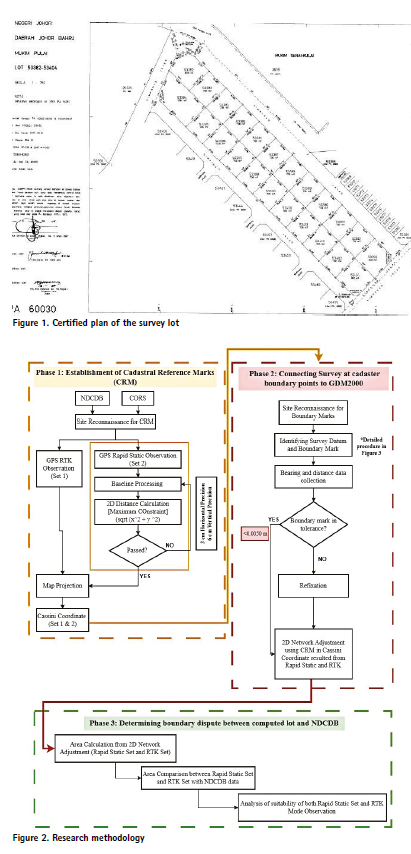
The study is for this research, as shown in Figure 1, is located in Taman Desa Skudai, Johor, and includes cadastral Lots 53382 53393 and 53394-53404. This area was selected due to its urban development and typical residential lot configurations, which present real-world conditions for assessing GNSS-based cadastral surveying methods. Additionally, the area’s proximity to existing Continuously Operating Reference Stations (CORS) within a 20km radius makes it suitable for evaluating the performance of both Rapid Static and RTK GNSS techniques. Lot data were obtained from the eBiz JUPEM portal to ensure consistency with official cadastral records.
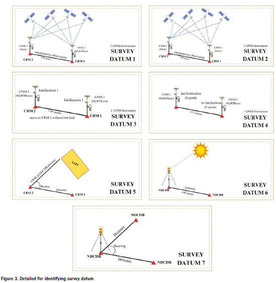
This study used National Research & Development CORS Network (NRCnet) and MyRTKnet. NRCnet was set up based on collaborative work amongst universities, government agencies, and positioning industries in Malaysia. MyRTKnet is Malaysia’s GNSS based network that provides real-time positioning services. It consists of a network of CORS distributed across the country. Both network offers satellite measurement correction in support of GNSS applications such as navigation and positioning [15]. This research has three (3) phases. Phase 1 involved using RTK and Rapid Static GNSS methods to establish CRMs, with data sourced from the NDCDB and linked to CORS stations. Phase 2 includes a traversing survey at cadastral lots using total station, while Phase 3 compared these findings with NDCDB data. The study analyzed duration, accuracy, precision, and area comparability of both methods. An overview of research methodology is illustrated in Figure 2.
In this research, two types of data were utilized. The first data comprises cadastral survey data, which consists of instrumentation calibration data, solar observations data, traversing data, and refixation data. The second data involves GNSS measurement; RTK and Rapid Static observation conducted over 30 minutes. These GNSS measurements are subsequently compared with the NDCDB provided by Department of Survey and Mapping Malaysia (Jabatan Ukur dan Pemetaan, JUPEM). Following data collection, the results are visualized using AutoCAD software to analyze the impact of both GNSS measurement methods and the NDCDB.
2.1 Phase 1: Establishment of Cadastral Reference Marks
The NDCDB is a comprehensive digital database managed by the JUPEM, containing cadastral and land-related information. The first step is data acquisition. In this step, two types of data are acquired which are NDCDB and CORS data. The NDCDB is obtained from JUPEM. Next, is to identify the nearest CORS from the survey area. Choosing the closest reference station optimized the signal quality and minimized potential errors, contributing to the overall precision of GNSS observations. Ideally, all CORS data should also be sourced from JUPEM if the station is located near the site.
Three (3) nearby CORS have been identified: JHJY, SPGR, and ISK1. Among them, JHJY and SPGR are part of the MyRTKnet network, and their coordinates can be accessed directly from the MyRTKnet website. ISK1, on the other hand, belongs to the NRCnet. All of these station coordinates are given in GDM2000. While NRCnet has demonstrated the capability to achieve centimeter-level precision, similar to MyRTKnet, external tests confirms that NRCnet’s precision is comparable to MyRTKnet’s high level of accuracy, making it equally reliable for applications requiring centimeter level accuracy. The coordinate solution in GDM2000 has been produced by [15]. Detailed network analysis can be found in the paper. However, in this study, one of the NRCnet station is chosen due to its closer proximity, ensuring higher accuracy and reliability for the measurements. Specifically, the JHJY from MyRTKnet and ISK1 from NRCnet stations were utilized to optimize data collection. Site reconnaissance is the next step to take before performing the GNSS survey. This step is to identify any potential challenges that might affect the survey process. It is essential to choose a suitable survey place that ensures a clear sky view and is situated away from the buildings. This can help to minimize multipath errors, which may impact the accuracy of the GNSS survey data. The quality can be quantified using Dilution of Precision (DOP). A DOP below 3 is essential for precise and dependable GNSS observations, especially in real-time positioning situations [16]
Two GNSS positioning methods have been applied in this study; Rapid Static and RTK method. In this case, four CRMs were established to form a stable and redundant geodetic control network, ensuring sufficient geometric strength for network adjustment and minimizing positioning errors. The number and distribution of CRMs were based on JUPEM’s cadastral survey guidelines. The RTK observation was connected to ISK1. The RTK data is real-time coordinates in GDM2000 that can be obtained directly at the survey area from the GNSS controller. The Rapid Static observation was conducted for 30 minutes on each point. This duration aligns with commonly accepted GNSS surveying standrads and guidelines, which suggest observation times of 15-45 minutes depending on satellite geometry, multipath environment, and baseline length. GNSS data were processed using the Trimble Business Centre (TBC) software. The Rapid Static observation was processed using the single baseline processing and connected to ISK1 and JHJY. The coordinates from the processed GNSS data were compared, and a 3D positional difference threshold of less than 3 cm was applied to ensure compliance with cadastral accuracy standards. This tolerance aligns with the accuracy requirements set by the JUPEM for first-order cadastral control points, and is consistent with international GNSS survey practices for high-precision applications. The final coordinates are calculated by averaging the coordinates of points based on two different CORS.
The coordinate of the GNSS measurement was transformed by using the Coordinates Transformation Program (CTP). The purpose of using this CTP software is to transform coordinates from GDM2000 into MRT48 and projected to Old Cassini Soldner. Steps for this datum transformation and map projection need to follow the survey regulation by JUPEM [17]. The parameters required for the transformation, including datum shift and ellipsoid parameters, were bought from the JUPEM, ensuring accuracy and official compliance in the transformation process.
2.2 Phase 2: Connecting Survey at Cadastre Boundary Points to GDM2000
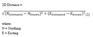
Before data collection, there are two important aspects involved, which are identifying the datum for starting a survey job and verifying the position of the boundary mark. Detail for identifying the survey datum is in Figure 3. The allowable displacement limits of boundary marks shall not exceed 10”. The cadastral survey datum is a standard requirement for conducting survey as a reference point for starting the cadastral work based on the requirement for survey outlined in PKUP2009 [18].
According to JUPEM, for a new survey to determine the coordinates, each cadastral survey should be based on qualified datum. Each cadastral survey should be based on a satisfactory datum consisting of one of the following options: (1) at least two CRMs points where distance is not less than 30 m with simultaneous observations by using MyRTKnet method for the f irst CRM and static method for second CRM, or (2) at least two CRMs points where distance at least 30 m, with simultaneous observations using the static method for both points, or (3) at least two newly established CRM points, where distance at least 30 m, with observations made using MyRTKnet for both points in the same initialization process. This process should be repeated in a second initialization, or (4) at least two CRMs where distance at least 75 m apart, with observations using either MyRTKnet in real-time or the static method for both points in two initializations, or (5) if two old CRM points are used, their positions must be verified by a third point using a bearing and distance observation, either from nearby old CRM points or from the National Digital Cadastral Database (NDCDB); or (6) two survey points from the NDCDB, where distance at least 40 m, where the original positions have been verified by direct measurements or traverse calculations, along with the sun observations for azimuth or MyRTKnet observations, or (7) two adjacent survey points from the NDCDB, where positions have been confirmed and verified by a third point using bearing and distance observations or traverse, with the points remaining in their original positions. This option ensures a reliable datum is established for precise and consistent cadastral measurements. Among the conditions stated to start the survey job is using two boundary marks with solar observations. The datum that needs solar observation is two boundary marks from NDCDB with distance not less than 40 meters where the original position of these marks has been proved by direct measurement or traverse [19]. Solar observations are only done when the sun’s altitude is at least 10°, either in the morning or in the evening. At least two sets of continuous observations of the sun are made. If there is a difference in grid bearing of more than 10” between the first and second sets, a third set is needed. Both crosshairs must be used to find the reference mark in each set of data. There should also be at least 30 m between the observation point and the reference mark that is being used. These simple rules make sure that the solar observations made during the study are correct and reliable.
After an acceptable tolerance is reached, data collection can be started by traversing around the lot. The survey qualities can be qualified as first-class if the misclosure does not exceed 1’15”. This error can be minimized by ensuring the face left and face right for every station reading does not exceed 10”. Every day before starting work, there must be a daily check in the field to make sure that the measures from the previous day are acceptable. According to survey regulations in 2009, this daily check should not exceed 0.01 m [18]. This ensures that any discrepancies or errors in previous measurements are identified and rectified promptly, maintaining the integrity and reliability of the survey data.
The final procedure is to conduct a refixation process. Refixation is the process of replacing boundary marks that has been found to move from its original position above the permitted limit. The limit of the displacement vector of the boundary mark is 0.05 m for urban or town and new development areas, while the limit of displacement vector for other areas is 0.10 m [19]. Before the refixation is carried out, the baseline must be identified. An allowable baseline must not exceed 30 m as stated in the regulation. After all the measurements have been carried out the next stage is to perform adjustment using Least Squares Adjustment. There are several criteria when adjusting, some of which are; (i) raw observation of bearing and horizontal distance will be used for adjustment. (ii) for minimum constraint, only one control station is constrained, and the rest are used for checking and (iii) for maximum constraint, all but one stations are constrained and the unconstrained station is used as a checking station. Checking is done by comparing the 2D distance between the estimated and known coordinate using equation 1. The output from the adjustment process contains the adjusted coordinates which help to achieve precise and dependable results for this study.
2.3 Phase 3: Determining Boundary Dispute between Computed Area Lot and NDCDB
The last phase is the area calculation that involves the adjusted coordinates obtained from the 2D Network Adjustment to compute the area of cadaster lots. These methods are also known as the Double Meridian Distance (DMD) methods that are used by the JUPEM as shown in equation 2.
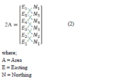
The Northing and Easting coordinates are listed and cross multiplied. The resulting data is then divided by two to obtain the area of each lot. The final step is the comparison of the area between Rapid Static mode, RTK mode, and data from the NDCDB. The acceptance tolerance between both GNSS measurement and NDCDB must not exceed 5% for areas under 40 hectares. The comparative analysis, through these steps, is instrumental in determining the suitability of Rapid Static and RTK mode for cadastral surveying in Malaysia.
3. Result and analysis
This section is divided into three subsections according to the achievement of the objectives of the study, which are; (i) CRM establishment. (ii) Connecting survey at cadaster boundary points to GDM2000. (iii) Determining boundary dispute between computed lot and NDCDB.
3.1 Phase 1: Cadastral Reference Marks Establishment
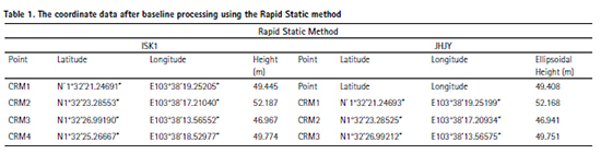
The coordinate for CRM1, CRM2, CRM3, and CRM4 in GDM2000 is shown in Table 1. The result in Table 1 shows the coordinates in latitude, longitude, and ellipsoidal height. Table 2 below describes the difference in the coordinates based on two CORS stations, which are JHJY from MyRTKnet and ISK1 from NRCnet. The coordinate is compared in difference northing (ΔN), easting (ΔE), and 2D distance.
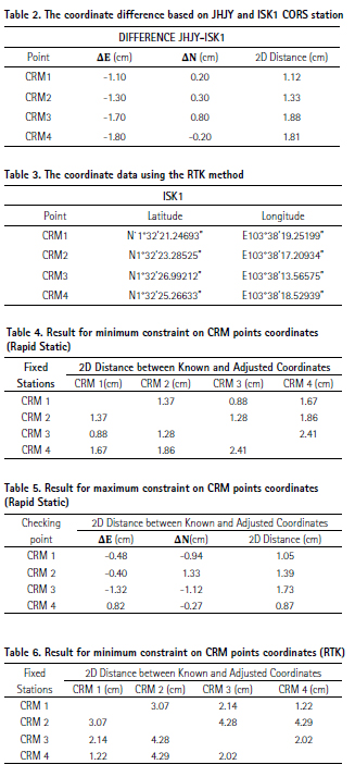
Based on Table 2, all the differences are generally small, with the maximum 2D distance difference is 1.88cm for CRM3. All CRM is below the acceptable range at 3 cm. The final coordinate used is from the average value from JHJY and ISK1. Table 3 shows the data for RTK that have been surveyed to four CRM points. RTK provides users with the coordinates only without a proper checking procedure. Further research can be done to propose a checking procedure for the establishment CRM using RTK.
3.2 Phase 2: Connecting Survey at Cadaster Boundary Points to GDM2000
Site reconnaissance was made at the survey lot, and it turns out that only two boundary marks were acceptable within the tolerance according to the survey regulation. Therefore, solar observations are performed to determine the true north direction. Two sets of sun observation have been carried out on station 2 with back bearing to station 1. The grid bearing to the sun of the first set is 150°22’45” while the second set is 150°22’41”. The difference between these two sets is 4”. The data is still in the tolerance that is required by the survey regulation. There were 10 stations established to form a closed closed-loop traverse. The result of bearing misclosure is 3”. The result of the misclosure is acceptable because the value is below 1’15” as stated in the survey regulation. The results of the computation of linear misclosure for the traversing shows that linear misclosure for the traverse is 1:19744, which exceeds 1:8000 and fulfills the requirement for the first-class survey. After a traverse survey, it was found that the 27 out of 42 boundary marks had either shifted from their original positions or were not found. Table 4 and Table 5 show the result of minimum constraint and maximum constraint for Rapid Static measurements respectively, while Table 6 and Table 7 present the minimum constraint and maximum constraint for RTK measurements.
Based on Table 5, the highest value for checking point using Rapid Static is CRM 3 which are 0.017 m. Meanwhile, in Table 7, the highest value for checking point using RTK is CRM 2 which are 0.029m. CRM 1, CRM 2, CRM 3 are used for maximum constraint. The 2D difference for this set is the lowest because its value is within the acceptance tolerance of 3 cm. The final coordinates of CRM are used in a Least Square Adjustment to determine the final coordinate of all the boundary points allowing to make area calculation. 2D Adjustment using Rapid Static performed better than RTK. This is because Rapid Static involves a longer observation time, which introduces measurement redundancy and allows for more accurate modeling of environmental factors, such as atmospheric delays and signal multipath effects, leading to improved baseline processing.
3.3 Phase 3: Determining Boundary Dispute between Computed Lot and NDCDB
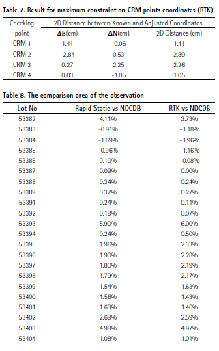
From the adjusted coordinates, the area of all the survey lots is calculated using the Double Meridian Distance (DMD) method. Table 8 shows the comparative analysis area of the survey lot areas as calculated by three different methods.
Based on table 7, lot no. 53382, 53393, and 53403 show the top 3 largest differences in terms of percentage. Lot no 53393 exceeds the 5% tolerance allowed by the regulations, which raises some concerns. The reference mark has shifted, which has affected the accuracy of the boundary measurements. This makes it crucial to carry out refixation to correct the survey data and ensure the boundaries are accurately marked. From the table 9, one can observe that the variations in the area comparison to NDCDB between Rapid Static and RTK are almost the same, implying that both techniques produce somewhat similar results. In most of the lots, RTK has larger variations than Rapid Static. Both GNSS measurement methods provide reasonable accurate areas.
A few lots show notable overestimation, which would need more research to determine the underlying reasons.
4. Discussion
The comparative analysis between Rapid Static and RTK GNSS methods shows that both methods achieve similar accuracy levels. These methods have their own pros and cons beyond just the accuracy. Rapid Static can make the surveying process more time-consuming compared to faster methods like RTK. One notable disadvantage of RTK GNSS is the lack of traceability. RTK gives real-time corrections without storing the raw data for post-verification. The lack of traceable data might cause errors in quality assurance, limiting the ability to perform detailed checks and corrections after data collection. Despite these disadvantages, both GNSS measurement methods demonstrate their effectiveness in cadastral surveying by achieving the 5% tolerance required for areas under 40 hectares, as specified by the regulations.
There are several limitations in the study, including the size of the lot selected, which is considered small. This restricts the ability to generalize the results to larger or more complex environments, where factors such as signal obstructions or longer baseline distances could impact the performance of both methods. Additionally, the use of only one CORS for RTK limits the ability to assess the effects of varying baseline lengths on positioning accuracy. Employing a network of multiple CORS stations would likely provide more comprehensive data, enhancing the understanding of how baseline variations affect GNSS accuracy, especially in larger surveys. Furthermore, the study utilized NRCnet rather than more widely adopted MyRTKnet, which may affect the applicability of the results to local GNSS applications, particularly in Malaysia.
Future studies could compare these two networks to explore differences in correction services and how they influence positioning precision. Lastly, the RTK GNSS data was collected during a single session using only the ISK1 base station. Conducting multiple sessions or establishing a second base station could have shortened the baseline and potentially improved the accuracy, providing more robust data for comparison. Despite these limitations, the study highlighted the effectiveness of both methods in achieving the required accuracy for cadastral surveying, while also identifying areas for further research and improvement.
5. Conclusion
This comprehensive analysis was able to achieve all the objectives through the three phases. For the first phase, four CRM were established and coordinated into GDM2000. As for the second phase, two sets of network adjustments were performed to get the adjusted coordinates based on the two GNSS positioning methods. Finally, for the third phase, an analysis of the suitability of both RTK and Rapid Static mode observations was made to achieve the aim of the studies. The results show that both methods achieved accuracy within the 5% tolerance limit, with Rapid Static providing slightly better precision. This suggests that the Rapid Static method may offer a more reliable approach for CRM establishments. The study’s limitations include using a small survey area, and the use of only one CORS. Future work will involve expanding the survey area, employing multiple CORS stations, comparing NRCnet with MyRTKnet, and conducting additional sessions or adding base stations to improve positioning accuracy.
Acknowledgement The authors would like to thank the Universiti Teknologi Malaysia for funding through the UTM Flagship CoE/RG Vot Q.J130000.5017.10G27, the JUPEM for providing the NDCDB data, Year 3 students from the session 2023/2024 who participated in the Survey Camp III course for their physical support in data collection and assisting with the survey work.
Funding
The support provided by Universiti Teknologi Malaysia for funding through the UTM Flagship CoE/ RG Vot Q.J130000.5017.10G27 for this study is highly appreciated.
Author contributions
Tajul Ariffin Musa: Idea and concept
Nur Alyya Nordin: Field work and Writing, Figures
Wan Anom Wan Aris: Analysis and Writing
Abdullah Hisam Omar: Discussion and idea
Muhammad Hafiz bin Mohd Yatim: Discussion and idea
Data availability statement
The data used to support the findings of this study are included within the article.
Conflicts of interest
The authors declare no conflict of interest.
References
[1] T. L. Choon, L. C. Ho, U. Ujang, T. A. Chin, N. S. Azri, K. S. Looi, et al., “An application of cadastral fabric system in improving positional accuracy of cadastral databases in Malaysia,” The International Archives of the Photogrammetry, Remote Sensing and Spatial Information Sciences, vol. 46, pp. 79–86, 2022.
[2] Jabatan Ukur dan Pemetaan Malaysia, “Isu-isu Pengukuran dalam Persekitaran eKADASTER dan Kaedah Penyelesaiannya,” Surat Pekeliling Ketua Pengarah Ukur dan Pemetaan Bilangan 1 Tahun 2010. [Online]. Available: https://www.jupem.gov.my/jupem18/assets/uploads/files/pekeliling/1b1fe-1-9.pdf
[3] M. Azhari, Z. Altamimi, G. Azman, M. Kadir, W. J. F. Simons, R. Sahaoine, et al., “Semi-kinematic geodetic reference frame based on the TFRF2014 for Malaysia,” Journal of Geodetic Science, vol. 10, no. 1, pp. 91–109, 2020.
[4] N. M. Hashim, A. H. Omar, S. N. M. Hamli, K. M. Omar, and N. Din, “Cadastral database positional accuracy improvement,” The International Archives of the Photogrammetry, Remote Sensing and Spatial Information Sciences, vol. 42, pp. 91–96, 2017.
[5] T. Li, H. Zhang, Z. Gao, Q. Chen, and X. Niu, “High-accuracy positioning in urban environments using single-frequency multi-GNSS RTK/MEMS-IMU integration,” Remote Sensing, vol. 10, no. 2, p. 205, 2018.
[6] W. Wielgocka, T. Hadas, A. Kaczmarek, and G. Murat, “Feasibility of using low-cost dual-frequency GNSS receivers for land surveying,” Sensors, vol. 21, no. 6, p. 1956, 2021.
[7] A. W. Mohamed Safith and L. De Silva, “The techniques and challenges of GPS surveying for vertical alignments in high-rise buildings,” International Journal of Building Pathology and Adaptation, vol. 40, no. 4, pp. 587–607, 2022.
[8] Y. Xu, C. Wu, L. Li, L. Yan, M. Liu, and S. Wang, “GNSS/PPP-BDS medium/long-range RTK constrained with tropospheric delay parameters from NWP model,” Remote Sensing, vol. 10, no. 7, p. 1113, 2018.
[9] D. Melgar, J. Geng, B. W. Crowell, J. S. Haase, Y. Bock, W. C. Hammond et al., “Seismogeodesy of the 2014 Mw6.1 Napa earthquake, California: Rapid response and modeling of fast rupture on a dipping strike-slip fault,” Journal of Geophysical Research: Solid Earth, vol. 120, no. 7, pp. 5013–5033, 2015.
[10] A. Elmezayen and A. El-Rabban, “Real-time GPS/Galileo precise point positioning using NAVSTAR real-time corrections,” Positioning, vol. 10, no. 3, pp. 35–49, 2019.
[11] D. Prochniewicz and M. Grzymla, “Analysis of the impact of multipath on Galileo system measurements,” Remote Sensing, vol. 13, no. 12, p. 2295, 2021.
[12] P. A. Zandbergen and S. J. Barbeau, “Positional accuracy of assisted GPS data from high-sensitivity GPS-enabled mobile phones,” The Journal of Navigation, vol. 63, no. 3, pp. 381–399, 2011.
[13] Y. Xu, “Integration of multi-constellation GNSS for long-range real-time kinematic positioning,” Ph.D. dissertation, The Hong Kong Polytechnic University, 2016.
[14] P. Fan, W. Li, X. Cui, and M. Lu, “Precise and robust RTK-GNSS positioning in urban environments with dual-antenna configuration,” Sensors, vol. 19, no. 16, p. 3586, 2019.
[15] T. A. M. Mohamad Afiq and A. A. Wan Aris, “Development of RGRF2018: Geocentric Datum of NRCnet,” 2019.
[16] T. L. Damanhajee, “The effect of multipath on single frequency C/A code based GPS positioning,” Engineering, Technology & Applied Science Research, vol. 8, no. 4, pp. 3270–3275, 2018.
[17] Jabatan Ukur dan Pemetaan Malaysia, “Garis Panduan Teknikal Mengenai Pemarkaan Koordinat, Transformasi Datum dan Ujuran Peta untuk Tujuan Ukur dan Pemetaan,” Pekeliling Ketua Pengarah Ukur dan Pemetaan Bilangan 3 Tahun 2021. [Online]. Available: https://www.jupem.gov.my/storage/upload-pekeliling/d9d14-pkpup-3-2021.pdf
[18] Jabatan Ukur dan Pemetaan Malaysia, “Peraturan Ukur Kadaster 2009,” Pekeliling Ketua Pengarah Ukur dan Pemetaan Bilangan 5 Tahun 2009. [Online]. Available: https://www.jupem.gov.my/jupem18/assets/uploads/2016/07/PekKPUPBil52009.pdf
[19] Jabatan Ukur dan Pemetaan Malaysia, “Garis Panduan Mengenai Ujian Alat Sistem Penentududukan Sejagat (GNSS) yang Menggunakan Malaysian RTK GNS Network (MyRTKnet),” Pekeliling Ketua Pengarah Ukur dan Pemetaan Bilangan 1 Tahun 2008. [Online] https://www. jupem.gov.my/v1/wp-content/ uploads/2016/07/Pekeliling12008. pdf#:~:text=Pekeliling%20 ini%20bertujuan%20untuk%20 memberikan%20garis%20panduan%20 mengenai,MyRTKnet%20bagi%20 kerja-kerja%20kawalan%20ukur%20 kadaster%20di%20negeri-negeri.
© 2025 The Author(s). Originally published by Universiti Malaysia Pahang Al-Sultan Abdullah Publishing. This is an open access article under the CC BY-NC 4.0 license
The paper is republished with authors’ permission.


 (2 votes, average: 2.00 out of 5)


Leave your response!