| Applications | |
Spoofing monitoring sensor for airports
This paper describes the innovative SMART (Spoofi ng Monitoring And ReporTing) sensor. The SMART sensor has been developed as part of the H2020 GMCA with main objective the enhancement of DW International’s GPMS monitoring system with the integration of interference and spoofi ng detection sensors |
 |
|
 |
|
 |
|
 |
|
In aviation, the extension of the utilization of GNSS that today is only a complementary system for air navigation and air traffic management systems has become the priority of many national plans. By 2030 it is expected that GNSS will be the main navigation system for most of the flight phases. GNSS is nowadays also as an essential component for other aviation systems, such as the Enhanced Ground Proximity Warning System (EGPWS) and Ground Based Augmentation System (GBAS). Navigation systems provide several advantages in aviation such as the increased safety and efficiency of flights. It is expected that GNSS based air routes will be able to accommodate up to three times the current traffic volume, [1]. Moreover, at remote locations, where traditional groundbased services are unavailable, airports approaches based on GNSS could be implemented providing increased operational and safety benefits.
Complementary to GNSS, Satellite Based Augmentation Systems (SBAS), that are scaled on aviation requirements, have been introduced to allow planes landing even during poor visibility conditions. Navigation signals performance and integrity monitoring is a consolidated functionality in the aviation domain, however, only few systems dedicated to spoofing monitoring have been designed and deployed. In the domain of critical infrastructure, several concepts and system architectures for interference and jamming monitoring have been designed and deployed, see for example [2]. However, only few solutions are known for the monitoring of spoofing threats. For example the GAIMS testbed has been prototyped with main objective to show importance to monitor the radio-frequency spectrum and to detect interferers increasing reliability and availability of GNSS and SBAS/SMGCS at airfields. Another solution, described in [3], presents a multi- layered and multi-receiver architecture that hardens GNSS-based timing against hazards with multiple spoofing monitoring technologies with effectiveness depending on the attack model. The main objective of the GMCA project is to extend the GNSS Performance Monitoring System (GPMS), developed by DW International, to include Galileo Monitoring. Moreover, the system has been updated to include the capability of interference and spoofing monitoring. Spoofing detection has been implemented using Qascom SMART sensor.
Overview of interference scenarios and contermeasures
GNSS monitoring is essential for increasing the availability and integrity of aviation applications. As wellknown navigation systems have several vulnerabilities. Vulnerabilities are commonly classified as unintentional and intentional interferences such as jamming and spoofing. .According to [4], dated 2003, successful spoofing and meaconing attacks are considered remote because of the complexity of the technology required. However, it has to be noted that, nowadays, the likelihood of occurrence of spoofing threats is increasing as the implementation of spoofers has become more feasible and less costly due to rapid advances in software-defined radio technology. In addition, the likelihood of success might increment with the level of sophistication of attacks.
As written in [RD5], the GIISST (GNSS Intentional Interference and Spoofing Study Team) has identified eight scenarios (collected in November 2012 DHS GPS National Risk Estimate). These are four Interference Scenarios and four Spoofing Scenarios (three intentional and one unintentional spoofing)
Details of the definition of the FAA scenarios are not publically available; however a high level classification is available in [RD7]:
• Pinpoint Spoofing Attack: already partially demonstrated (research, test for hovering UAV with non-aviation grade equipment and pre- determined knowledge of vehicle position/time)
• Coordinated Spoofing Attack: no known event for civil, approved, aviation applications
• Coordinated Interference and Spoofing Attack: no known event for civil, approved, aviation applications
• Unintentional Re-radiator: this is caused by malfunctioning or improper use of GPS re- radiators or pseudolites typically installed in the airports. This impact mainly the taxiing and take- off fiight phases.
Spoofing and meaconing threats could be critical in terms of aircraft system impacts, as they might lead to the avionic receivers issuing hazardously misleading information (HMI). Indeed, potential erroneous position might be output to primary flight displays/indicators and other aircraft and ATC systems. Moreover, conventional RAIM is only partially effective against GPS spoofing. FAA scenarios have been considered as reference also in the project. However, for the prototyping activities two main spoofing scenarios have been analyzed:
• Intentional Spoofing during Approach
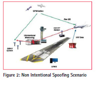
• Non Intentional Spoofing during Taxi-In or Take-Off
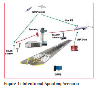
Intentional Spoofi ng during Approach
Depending on speed of the aircraft, availability of weather information, and the complexity of the approach procedure or special terrain avoidance procedures for the airport of intended landing, the in-flight planning phase of an instrument approach can begin as far as 100-200 nautical miles (NM) – from the destination, [6]. An instrument approach may be divided into four approach segments: initial, intermediate, final, and missed approach.
The ILS system is, nowadays, the primary system for instrumental approach for category I-III-A conditions of operation and it provides the horizontal as well as vertical guidance necessary for an accurate landing approach in IFR (Instrument Flight Rules) conditions, thus in conditions of limited or reduced visibility. The major risk for aircraft navigation (most likely during bad visibility conditions) is at the beginning of the approach phase. Assuming the SMART is located and operated in the airport area, this will be capable to detect spoofing events whenever the spoofing signals, which are targeting the airplane, reaches also the sensor antenna.
This scenario, drives the spoofing detection algorithms configurations as:
• Spoofing Doppler could have an offset of several KHz from the authentic.
• Spoofing delay might have an offset up hundreds of chips from the authentic
• Spoofing power offset depends on the relative distance between the aircraft under attack and the sensor
Non Intentional Spoofing during Taxi-in or Take Off
Certain non-aeronautical systems transmit radio signals intended to supplement GNSS coverage in areas where GNSS signals cannot be readily received (e.g. inside buildings). These systems include GNSS repeaters and pseudolites. GNSS repeaters (also known as “reradiators”) are systems that amplify existing GNSS signals and re-radiate them in real-time. A case of interference has occurred in Germany, in 2012, due to a malfunctioning of a GPS repeater operated in a hangar of Hannover. airport The interference caused alerts of the Enhanced Ground Proximity Warning System providing the messages ”pull-up” and ”FMS/GPS Position disagree” during Taxi-in and departure of the airplanes. With an EIRP of the GPS repeater in the order of -60 dBm (to be confirmed) the interference range was several hundred meters. The operation of the GPS-repeater has been suspended until the end of the investigation. It has to be verified whether the EIRP limit of -77 dBm as stipulated in the draft ECC recommendation ECC/REC/(10)02 would have ensured sufficient protection. Several other events have been recorded in the US.
At the sensor position the reception of the unintentional spoofing signals depends on the malfunctioning of the repeater and generating GNSS signal with higher power (e.g. 20 dB to 30 dB). From the signal point of view, non- intentional spoofing is equivalent to meaconing.
Spoofing Contermeasures
As written in [7], FAA will require that future aircraft equipment to cease GNSS use when intolerable interference or spoofing is detected. Several countermeasures against intentional interference can be addressed, [4]; these could be operational mitigations that require the integration with other airborne systems (e.g. GPWS, TCAS, etc…) and methods at receiver. Even low- complexity techniques could reduce the vulnerability to spoofing. Examples are: AGC/SNR valid range, PVT checks, additional channels to detect presence of duplicate PRNs, navigation data simple checks or antenna technologies can reduce vulnerability to spoofing and interference. At system level also the introduction in GNSS and SBAS on navigation message authentication will provide benefits for aviation.
Spoofing monitoring sensor description
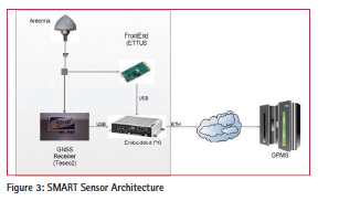
Figure 3 shows the high level architecture of the sensor.
The sensor is composed by:
• an Antenna for the collection of GNSS signal in space, spoofing signals and interference in the E1 band. The antenna signal is input to the RF Digitizer and the GNSS Receiver.
• a High End RF Digitizer: the board is capable of sampling RF signals with a high resolution ADC. This module receives commands coming from embedded PC and it sends IQ samples to the same device using an USB3 link.
• a GNSS Receiver: the receiver that processes the GNSS signals, generating raw data and PVT that are sent to the embedded PC via USB.
• an Embedded PC that runs the main SW modules including:
– SDR based spoofing detection techniques
– PVT and observables spoofing detection
– IQ data batches collection
– communication with the external central processor
The sensor is designed to acquire batches of samples configurable length (i.e. 50ms), in E1/L1 band, at a configurable rate (i.e. 1 Hz). Monitoring of GNSS signals is achieved in real-time. Any detection of spoofing signals raises an alert that is forwarded to the central server. At the same time, the sensor collects the observables and PVT data from the GNSS receiver and uses also these data to monitor the presence of spoofing signals. The sensor software has a high level of configurability. Moreover the application is hardware independent except for the interface with external devices (GNSS Receiver, Front End). The communication with the GPMS system is managed by the Server Interface that exchanges with the GPMS main controller the following XML messages via HTTP:
• Output Configuration containing Sensor Position, General settings, Front End settings and Spoofing Detection techniques settings
• Sensor Status containing the status of the sensor that is regularly sent
• Spoofing Data that collects the spoofing detection flags and metrics for all the Satellites in view, generated at the rate of 1 Hz.
• Input Configuration that is the configuration message of the sensor that can be written by the GPMS controller to configure sensor settings and enable/disable the spoofing detection techniques.
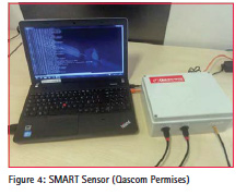
Figure 4 shows a prototype of SMART sensor. The software runs in the laptop that is connected with the Front End and the GNSS Receiver.
Spoofing detection techniques
The spoofing detection engine has been designed according to the following requirements:
• Capability to Monitor Spoofing with:
– Power Offset: between -3 dB and +15 dB. Lower bound is related to receiver acquisition sensitivity, upper bound is a limit over which the spoofing signal can be considered as an interferer.
– Frequency Offset: related to the maximum relative velocity between the sensor and a plane during the approach phase.
– Delay Offset linked to common distance from the airport of the approach phase beginning.
• Spoofing Detection probability 95% and False Alarm lower than 10-4
• Time to Alarm lower than 5 seconds.
The spoofing detection engine is the core element of the SW. This includes five different methods operating at IQ level, observables levels and PVT level.
IQ Level Spoofing Detection
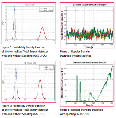
At IQ level, two spoofing detection techniques have been integrated. These use as input the batches of samples collected with the RF digitizer. The first approach is the Multi-Peak detector: in presence of spoofing, the Acquisition Cross Ambiguity Function (CAF) has two peaks. The first step of the detection algorithm is the estimation of Doppler and code phase of the CAF bin that has the maximum magnitude, above the acquisition threshold. Then the peak (that could be the authentic or the spoofing one) is cancelled out from CAF and the algorithm proceeds with the estimation of the second highest peak. In case a secondary peak is detected, spoofing is declared. The second method is the Total Energy detector. The algorithm is based on the computation of the sum of the correlation values power. To detect the presence of spoofing this value is compared with the total estimated power in nominal conditions. Figure 4 and Figure 5 show the probability density function (PDF) of the normalized total energy indicator under hypothesis H0 (no spoofing) and H1 (presence of spoofing) for GPS L1 and Galileo E1B. An optimized procedure to monitor all satellites in view or non in view (the spoofer can generate satellites that are not visible to the sensor) has been integrated. The satellites are divided in two groups (in line of sight and non-line of sight ) and the monitoring is done with different periods on the two groups.
Observable Level and PVT Level Spoofing Detection
Two observable level and one PVT level spoofing detection methods have been introduced in the SMART sensor SW. These solutions use as input C/N0, Doppler and the PVT generated by the GNSS receiver.
The Power Threshold Detector is based on monitoring the change of a satellite’s signal power. The method estimates the moving variance of the observed signal that is a metric that is sensitive to the transition between the legitimate and a spoofing signals.
The second method is a Doppler Threshold Detector that as for the Power threshold detector, is based on the computation of the moving variance of the Doppler. Doppler offsets can indicate the beginning of a spoofing attack, when an adversary is trying to make the GNSS receiver lock onto the false signal.
The third method is the PVT detector. This method is based on the check between the estimated Position and the reference Position of the sensor that is known a priori.
A weighted majority voting approach has been proposed to generate a unique detection flag using all the spoofing detection methods’ outcomes. Moreover, to maximize the spoofing detection the application of Weighted Majority Voting is of benefit also in improving spoofing detection probability between different tracking channels. The baseline assumption is that if one satellite is spoofed it is highly probable that also others are spoofed.
Table 2 reports a mapping between the expected effectiveness of spoofing detection techniques and the spoofing scenarios identified.
The main findings, during preliminary simulation assessment, are that Multipeak approach is particularly effective in case of Intentional attack in the approach phase because the Doppler and Code Phase separation between authentic and spoofing signals is high. The Total Energy approach is considered complementary as this detector computes the energy near the acquisition matrix peak which is particularly effective for non-intentional spoofing. The PVT Check is considered ineffective for intentional spoofing as it is unlikely that the GNSS receiver channels lock on spoofing signals. Power and Doppler methods are considered only complementary as they are capable of revealing spoofing only during the transition between authentic to false signals in the tracking channels.
Simulation and test results
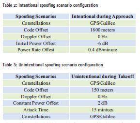
The SMART sensor is being validated using radio navigation laboratory equipment. In particular a Spirent Constellation simulator GSS6700 in connection with the SimSAFE software tool (developed by Qascom and distributed by Spirent) has been used to test spoofing scenarios. SimSAFE represents an innovative approach to the simulation of attacks, the test of detection techniques and signal authentication schemes, permitting maximum flexibility and the opportunity to leverage existing Spirent RFCS equipment. SimSAFE controls Radio Frequency Constellation Simulator (RFCS) hardware in order to emulate signal simulation attacks and test receiver mitigation techniques. SimSAFE allows flexibility in the attack scenario definition and test of interference detection techniques. The following two scenarios have been simulated to emulate the Intentional and Unintentional spoofing scenarios.
Spoofing is generated on six channels for each constellation (GPS and Galileo) with the objective of demonstrating the detection capability of the implemented spoofing detection methods. Table 3 reports the main parameters of the Intentional Spoofing Scenario. Figure 8 shows the global detection flags using the weighed majority voting between all spoofing detection algorithms for Galileo visible satellites. The plot lines are green when spoofing is not detected whereas the line is red when spoofing is detected. Figure 9 shows the output test values for the five spoofing detection methods implemented in the SMART sensor. It is resulted that only the Multi peak algorithm detects the spoofer, as expected, with a spoofing detection probability higher than 95%.
Table 4 reports the main parameters of the Unintentional Spoofing Scenario.
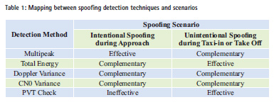
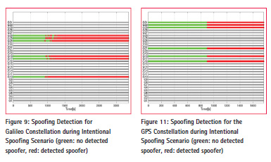
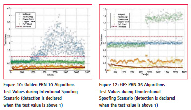
Figure 10 shows the global detection flags using the weighed majority voting between all spoofing detection algorithms for GPS visible satellites. The plot lines are green when spoofing is not detected whereas the line is red when spoofing is detected. Figure 11 shows the output test values for the five spoofing detection methods implemented in the SMART sensor. It this scenario, the Total Energy algorithm detects the spoofer as expected, with a probability of spoofing detection higher than 95%.
The experimental results confirm that the Multi peak solution is adequate for intentional scenarios whereas the Total Energy solution is more effective in unintentional cases.
Conclusions
This paper describes the innovative SMART (Spoofing Monitoring And ReporTing) sensor, designed and engineered by Qascom for critical applications, with primary focus on airport infrastructures. The sensor embe ds effective spoofing detection mechanisms at IQ, observable and PVT level. The signal processing is optimized to ensure adequate missed detection probabilities and very low Time to Alarm as per the ICAO standards. Qualification test results in representative test scenarios have been shown. Several evolutions have been envisaged for the proposed technology such as multi- frequency capability in particular for GPS/SBAS L5 and Galileo E5a and the introduction of the spoofing direction of arrival capability based on a dual antenna configuration.
Acknowledgment
GMCA project has received funding from the European GNSS Agency under the European Union’s Horizon 2020 research and innovation programme under grant agreement No 641613. The authors would like to acknowledge the GSA project officer and project reviewers for their support to the work.
References
[1] ICAO Working Paper, “Dependency on GNSS of Future Air Navigation Systems and Measures for its Vulnerability”, 31/10/2012 12th Air Navigation Conference
[2] S. Fantinato, S.Montagner, G.Gamba, A. Dalla Chiara, O.Pozzobon, Filippo Rodriguez, “Defending Critical Infrastructures from GNSS Interference” Ka Band Conference Proceedings 2015
[3] Liang Heng, Daniel Chou and Grace Xingxin Gao, “Reliable GPSBased Timing for Power Systems, Inside GNSS, Nov. 2014.
[4] Eurocontrol Experimental Centre, “GNSS SOLE SERVICE FEASIBILITY STUDY”, Project GNS-Z-SBAS EEC Note No. 04/03 May 2003
[5] D. Lawrence “FAA Navigation Programs Update”, Presented to: CGSIC September 17, 2013
[6] F AA Manuals, Approach Procedures, http://www.faa.gov/regulations_ policies/handbooks_manuals/aviation/
[7] D. Lawrence, FAA Navigation Programs Update, October 2014
[8] G. Gamba, S. Fantinato et al, “The Spoofing Estimating Delay Lock Loop”, proceedings of Navitec 2014
[9] Aleksandar Jovanovic, Cyril Botteron, Pierre-Andre Farinè, “Multi-test Detection and Protection Algorithm Against Spoofing Attacks on GNSS Receivers”, ION PLANS, 2014


 (No Ratings Yet)


Leave your response!