| Positioning | |
Quality evaluation of NRTK correction transmission
|
||||
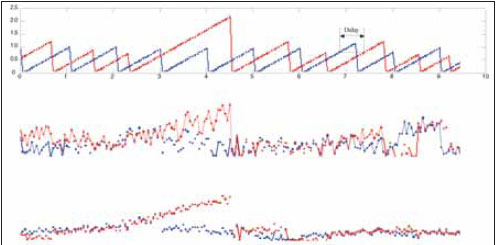
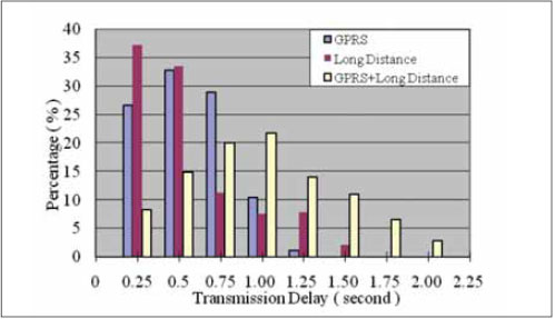
GNSS positioning/navigation devices are rapidly merging into and changing our modern lives, just like the personal computer in the 1980’s and the cellular phone in the 1990’s. It is predicted that by 2012, the annual shipment of navigation devices will increase to over 65 million units, which is more than three times the 19.8 million shipped in 2006 [1]. Also in a situation personal computer and cellular phone ever faced, a higher standard service demand has been placed in front of the GNSS technology, and becoming a bottleneck before its potential mass market can be exploited. More precisely, at present, real time and high accuracy are the two major concerns for many promising commercial GNSS plans, such as Road Pricing and Intelligent Transportation Systems Services (ITSS) [2]. For these high demand applications, Real- Time Kinematic (RTK) positioning is one of the most signifi cant solutions and has been widely tested and commercialized in many countries [3-5]. Its latest evolving trend has been leading in the Network RTK (NRTK) direction. NRTK technology can remove spatially correlated errors and effectively mitigate distance-dependent errors in the GNSS measurements, and achieve a centimetre-level positioning solution [6]. In such a high accuracy real time system, reliable and high-speed server-rover communication (i.e. correction message transmission) plays an important role in the fi nal performance. Our work will investigate the quality variation of the NRTK correction transmission, and reveal its influence on the positioning solution. NRTK backgroundIn the traditional RTK technology, by differencing the carrier phase observables between the receiver and a reference station with known high-accuracy position, spatially correlated errors can be removed, and positioning accuracy can be improved from tens of meters (Stand Alone mode) to centimetre level. The limitation of traditional RTK is that some distance-dependent errors (such as ionosphere delay) will increase with the increasing length of the baseline between the rover and the reference station. Normally for an implementation with centimetre-level accuracy requirement, the baseline length should not be more than 20km [2]. For national GNSS applications, this limitation would result in a dense reference station network and considerable investment in infrastructure. To overcome this constraint, NRTK was developed in recent years. In a NRTK GNSS facility, a central data server collects the raw observations from a number of reference stations, and sends corrections to a rover positioning terminal after carrying out an integrated processing. The rover then combines these corrections with its local carrier phase observations, to obtain a high accuracy real time positioning solution. The architecture of NRTK system is shown in Figure 1. In a NRTK implementation, through the interpolation of corrections from a set of reference stations, the distancedependent errors are mitigated and the high-accuracy solution can be achieved in a much greater area than a traditional RTK implementation. The separation between the NRTK reference stations can be extended to 100km [7], which means only 600 stations could cover the whole European area. Data disseminationMuch research in NRTK technology has focused on the efficiency and effectiveness of the reference stations measurement usage, through improving models (especially for the ionosphere model) and the data processing technique to reduce the number of stations and cost. When a network is getting sparse, the length of data communication will extend accordingly. In the meantime, due to the rapid change of the satellite geometry and also the atmospheric conditions, the correction messages from the data server have a time-limited validity. Thus the challenge for NRTK data dissemination is to keep a reliable and high speed wide-bandwidth service in a long distance transmission. The variations during the correction data transmission, i.e. message delay and loss, may increase with the increase of the baseline and eventually degrade the high accuracy solution. Therefore the quality of the RTK correction data dissemination should be taken seriously. The RTK data transmission channel is a combination of cable connection and wireless connection. In terms of the cable connection part, public Internet is the dominating choice. In 2003 an application-level protocol, Network Transport of RTCM via Internet Protocol (NTRIP) was developed by the Federal Agency for Cartography and Geodesy (BKG), Germany [8]. It is dedicated to streaming GNSS data over the Internet. The data server of a RTK network is both a TCP/IP server and an NTRIP caster. In terms of the wireless connection part, there are several available transmission methods which can be utilized for NRTK positioning [9]. Table 1 includes the comparison of the major features of these methods and it can be concluded that only commercial cellular communication and satellite communication can be used in the large area applications. Comparing these two methods, the former has great economic and practical predominance at the current stage. Among the various mobile networks in today’s market, the GPRS (EDGE) and 3G network are the best options [10] and the former has a further advantage in the service coverage. Currently both public Internet and GPRS can provide high-quality services. However, these services are not guaranteed. RTK data does not have any priority on these channels, although it is quite time-sensitive. During the transmission, frequent route switching, channel congestion in peaktime and even any faulty from the service provider’s equipment might cause the RTK messages to be delayed or lost. Evaluation SystemTo study the impacts of these transmission variations, parallel tests were conducted using the setup as shown in Figure 2 in a research lab within the Institute of Engineering Surveying and Space Geodesy (IESSG) in the University of Nottingham. The tests were carried out in a static NRTK mode with a GNSS antenna fi xed on a precisely measured point to minimize the infl uence from irrelevant factors. The whole system can be separated into three sections: Data Source, Data Dissemination Route and Data User. In the data source section, a dedicated RTK GPS network established jointly by the IESSG and the Leica Geosystems is utilized. This network consists of 14 high grade geodetic GNSS station sites and covers an area of Table 1: Comparison of Different Correction Dissemination Approaches Figure 2: Evaluation System Design Figure 3 Data latency and corresponding horizontal and vertical errors; Blue : Benchmark solution, Red: GPRS + Long Distance solution ~20,000 km2 in the Midlands region in the UK. The raw observations from these site servers were sent to an NTRIP caster in the central data processing centre, which is located in the IESSG. Professional NRTK software Leica Spider v3.0 was adopted to organize the raw data, generate correction data for any receiver request and disseminate the correction messages in the Radio Technical Commission for Maritime services (RTCM) format. In the data dissemination section, four different transmission scenarios are considered. The fi rst one is through a short local Ethernet link, in which case the cabled connection between the receiver and the NRTK server is only tens of meters long, and can simulate an ideal transmission link. This transmission is assumed to have zero message loss and delay, and is used as a benchmark to compare with the other three transmissions. The second confi guration is through a commercial GPRS link, where the receiver communicates to the NRTK server via a dedicated cellular modem. The third confi guration is through a long-distance public Internet link. In this scenario the RTK data is relayed via a remote NTRIP caster which is located at the Finnish Geodetic Institute (FGI), Helsinki, Finland, and sent back to the receiver. The public Internet link used here is over 2000km long. This scenario is designed to simulate a rigorous cabled connection environment. The last configuration is a combination of the second and third setting, i.e. a longdistance public Internet plus a GPRS link. The RTK data is sent to the remote NTRIP caster in Helsinki and sent back to the receiver via a commercial GPRS link, which can represent a typical commercial NRTK correction transmission. Figure 4 Distribution of the message delay Table 2 Statistics of the message delay and loss Table 3 Statistic of the horizontal error Table 4 Statistic of the vertical error The second confi guration is through a commercial GPRS link, where the receiver communicates to the NRTK server via a dedicated cellular modem. The third confi guration is through a long-distance public Internet link. In this scenario the RTK data is relayed via a remote NTRIP caster which is located at the Finnish Geodetic Institute (FGI), Helsinki, Finland, and sent back to the receiver. The public Internet link used here is over 2000km long. This scenario is designed to simulate a rigorous cabled connection environment. The last confi guration is a combination of the second and third setting, i.e. a longdistance public Internet plus a GPRS link. The RTK data is sent to the remote NTRIP caster in Helsinki and sent back to the receiver via a commercial GPRS link, which can represent a typical commercial NRTK correction transmission. In the data user section in Figure 2, a geodetic Leica 1200 receiver was employed. Its outputs are provided in NMEA $GPGGA format at 20Hz and are logged by a PC. Besides the positioning solution, the data latency, or the “age of correction” (i.e. the elapsed time from the time of the latest RTK correction to the time of the current solution made [11]) is available in the GGA sentence and can be used to determine the message delay. To avoid the infl uence of irrelevant factor, the parallel tests are carried out at the same time, and utilizing the same type of receivers, sharing a common GPS antenna and keeping all the same configurations except the transmission methods. Therefore differences between the benchmark and the other three solutions are only caused by the transmission variation. Also, although the solutions are made in the RTK mode, all the tests are carried out as static, to avoid the unnecessary kinematic disturbance. |
||||
Pages: 1 2


 (No Ratings Yet)


Leave your response!