| Navigation | |
Harbour navigation
|
||||
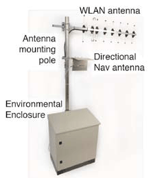
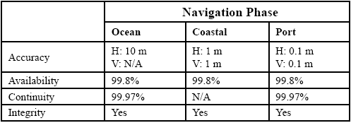
Certain emerging navigation performance requirements for maritime applications are challenging to satisfy using systems available today. Very stringent performance requirements have, in particular, been identified for port areas, and cover aspects including service robustness, accuracy, integrity and availability. One promising answer may be to augment GPS coverage with a groundbased Harbour Navigation System. In the Spring of 2008 EADS Astrium demonstrated a prototype for such a System, using transmitters based on navigation Pseudolite technology. This paper focuses on the potential for a Harbour Navigation System to augment GPS for harbour operations. The paper was derived from several recent publications [1-4] by the same author and colleagues from Astrium’s Portsmouth offices. Emerging maritime user requirementsCertain emerging navigation performance requirements are considered beyond the capabilities of GPS to support. Figure 1: Maritime HNS Configuration Identified applications in port areas (for example automated docking) have very stringent performance requirements as shown in Table 1. The figures are based on an analysis conducted in Project MARUSE [5] , and are compatible with figures from the International Maritime Organisation (IMO). GPS performance today is suitable for the Oceanic Navigation Phase; for the other Phases, however, GPS cannot reliably meet requirements for accuracy or integrity. In addition, the demanded availability and continuity are impossible to meet using GPS alone in Port areas unless user vessels have a continuously clear sky view. In many Ports, various objects including high buildings, gantry and other cranes, and bridges, may obstruct the sky view for user vessels, potentially blocking GPS satellite signal reception and causing a navigation coverage outage. Harbour Navigation SystemHNS concept The Harbour Navigation System (HNS) Figure 2: Transmit Station Physical Realisation concept created by Astrium is for a Navigation System compatible with, but independent from, the GPS System. Users are able to navigation using HNS alone, GPS alone, or a combination of the two systems together. EADS Astrium recently developed and demonstrated the use of an HNS. This included: • A number of Transmit Stations mounted at accurately known locations overlooking the operation / demonstration zone. These transmit GNSS-like signals, typically pulsed to minimise any interference. • A single Monitoring & Control Station with line of sight visibility of each Transmit Station. In Figure 1 the configuration of the HNS is illustrated. This includes several synchronised Transmit Stations, a Reference Station, a Monitor and Control Station, and the wireless network interconnecting them (although wired interconnect may be equally valid for fixed installations). A navigation solution can be obtained at a user receiver from a mixture of GPS and HNS signals. In addition to any onvessel equipment, the HNS has its own GNSS receiver to provide references to the M&C facility. These receivers used conventional GPS L1 transmissions as well as the HNS transmissions to maximise system robustness. Table 1: Example Maritime Application Requirements (extract from [5]) Figure 3: Demonstration Scenario (figure courtesy of Dr Alan Grant General Lighthouse Authorities of the United Kingdom and Ireland) HNS benefits The HNS can bring a number of benefits to Harbour Operations. These include the following: • The HNS is a locally controlled and fully independent Navigation System. • The HNS is scalable to larger or smaller coverage area. Transmitter powers can be increased or decreased to change the coverage provided. The HNS is also scalable to add more Transmitters if wanted, for example to provide a shaped coverage. • The HNS is fully interoperable with GPS, but HNS operation permits local navigation if GPS were unavailable or suffered some problem. • The primary usage model is based on a combined GPS / HNS Receiver on Ships or Pilot Portable Units. RF parts of the receiver are identical, as are signal processing parts, and items such as the display. New software is, however, needed to process the HNS measurements. Hence the cost impact on User Equipment is minimal. Operationally it is foreseen that users will use GPS anywhere, and will then switch to combined GPS & HNS in harbour areas. • The HNS facilitates robustness to interference and to GPS “Black Holes”. Power Control can increase signal levels; in addition, the HNS can operate on different frequencies if user equipment is configured to support this. In terms of GPS “Black Holes” (regions where local obstructions cause problems with GPS reception), the HNS mitigates the problem by placing Transmitters close to where there are GPS problems • There is also potential to extend HNS capabilities by relaying GPS differential corrections and/or RTK and/or Integrity data over the HNS transmissions using spare capacity in the transmission channel. Transmit stations The Transmit Stations are a variation of navigation pseudolite technology. They are compact and self-contained, and produce GNSS satellite-like transmissions at a source level that is preset and generally maintained constant. Transmitters are generally synchronised in groups to work together as a single, coherent system. The design places few restrictions on the location of their deployment, ensuring that planners have the freedom to create optimal signal environments for maritime or other sector applications. Monitor and control station The Monitoring & Control (M&C) Station coordinates the operation of Transmit Stations so that they form a coherent navigation system. At the heart of the M&C Station is a processing element with the ability to accept and process data from a GNSS Reference Receiver. The data received includes measurements of Pseudorange, Carrier Phase, Doppler, C/No and lock time; data such as raw Navigation symbols and tracking & receiver status. The M&C also generates commands for dissemination to each Transmit Station, for passing of navigation parameters and miscellaneous data. Linked with this is the mechanism for accepting and processing acknowledgements and other health & status data from each of the transmit stations received via the communications link. Reference station Core to the Reference station was a Septentrio GeneRx Receiver, capable of tracking GPS satellites as well as transmissions from the pseudolites. Its main function are to measure Pseudoranges from the transmit stations, to collect the transmitted Navigation Data, to time-stamp this data and to relay it to the M&C Station.A Communications Link interconnects the M&C Station with each of the Transmit Stations at their remote locations. For the prototype equipment, X8200 Radio Modems were used. Serial data can be transmitted with baud rates from 1.2K to 115.2K over distances of 10km to 20km line of sight, and can operate in both licenseexempt and licensed bands. Antennas used are 10dB Yagi at the Transmit Stations and 0dB omnidirectional antenna at the M&C Station. For an operational system this link type may be appropriate, or may be replaced by a domain-specific or fixed-line link. HNS signalsThe Signals transmitted for the Oban demonstrations were based on Galileo transmissions. In the HNS, there will of course be no ionosphere between the Transmit Stations and the Receivers; it is therefore of limited value to use multiple transmission frequencies. The transmissions used were identical in terms of frequency and modulation to Galileo transmissions [6]. They comprise two pairs of I&Q components referred to as E5A and E5B, which are AltBOC modulated onto an RF carrier centred at 1191.795 MHz.. The navigation message content was adapted to cope with the Transmitters being stationary. |
||||
Charles S Dixon
|
|||||||||||||||
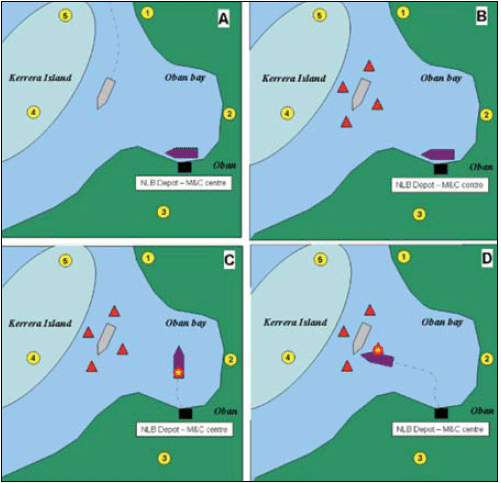
Oban demonstrationsDemonstration overview Tests and live demonstrations took place in Oban on the West coast of Scotland, in March 2008. Observers from around Europe saw NLV Pharos undertake a variety of precision manoeuvres in the bay. These included placement of a wreckmarking buoy. Crucial to the success of the demonstration were a number of new systems developed under the MARUSE project, including innovative onboard dynamic positioning technologies and an array of EADS Astrium pseudolites which mimicked Galileo satellite signals. The pseudolites were placed in various locations around Oban Bay, enabling the vessel to use Galileo-like signals for the first time to navigate in British waters. Participants watched the NLV Pharos in real time via closed-circuit television as it manoeuvred. The demonstration was hosted by the Research and Radionavigation Directorate of the General Lighthouse Authorities of the UK and Northern Ireland (GLAs), which include the Northern Lighthouse Board, the Commissioners’ of Irish Lights and Trinity House. Demonstration scenario The public demonstration was based on the concept of action taken to deal with a vessel blocking a busy waterway. It used a combination of HNS pseudolites, GPS and Virtual Aids to Navigation (making use of AIS and Electronic chart displays). The demonstration also used NLV Pharos vessel to undertake the physical demonstrations within Oban Figure 4: NLV Pharos deploying a wreck marker buoy during Oban Demonstration (photo: Dr CS Dixon, EADS Astrium) bay. The scenario for the demonstration is illustrated in Figure 3 and described below: • A simulation of a vessel entering the Oban waterway (using AIS to show its position) is shown on an ECDIS electronic chart display. • (Diagram A) The simulated vessel suffers a failure causing it to remain in the waterway as an obstruction. • (Diagram B) The position of this vessel is marked by the GLAs using the virtual AtoN and its position is broadcast via AIS to all nearby vessels. • (Diagrams C and D) The NLV Pharos is deployed to physically mark the vessel with a Buoy, over the same location as that provided by the Virtual AtoN, using the enhanced positioning from the EADS Astrium Pseudolites. ResultsFor the Demonstrations, code-tracking accuracy was recorded as approximately 2 metres or better. There were measurement and other difficulties; however, subsequent analyses have shown that this accuracy can be reliably achieved. In an operational system, it would be possible to operate using this code-tracking method, or instead to track the carrier signal. Carrier tracking methods have been widely employed in high-precision GNSS applications for some time and yield higher accuracy but lower robustness than code-tracking methods. In separate experiments, EADS Astrium Transmit Station signals have been carrier-tracked with accuracies around 15cm. This was not done for the Oban Demonstrations, but is indicative of what could be achieved if wanted in an operational system. Conclusions and future workA Harbour Navigation System was created by EADS Astrium and was successfully demonstrated with several partner companies as part of GSA Project MARUSE. The demonstrations reported here were undertaken in Oban on the West Coast of Scotland in spring 2008 as part of Project MARUSE. This used Pseudolite Transmission Stations and M&C Station equipment developed by EADS Astrium and described in this article, Receivers from Septentrio, User Terminals from Kongsberg Seatex, and Vessels from the Northern Lighthouse Board.HNA equipment comprising Pseudolite-based Transmit Stations and M&C Station Equipment have been added to the EADS Astrium product range. Future work includes confirming market applicability for various domains and commercialisation of the equipment. Future adaptations of the Equipment for other domains are foreseen. This may include Emergency Management, Rail, Road, and Security-related domains. References[1] Dixon, C.S.: A Maritime Harbour Navigation System based on Pseudolite Transmitters. International Symposium Information on Ships ISIS 2008, September 2008, Hamburg, Germany [2] Dixon, CS and RG Morrison; Demonstration of a Galileo-Based Maritime Navigation System: First Demonstration Results. ENC GNSS 2008 Toulouse, France, April 2008. [3] Dixon, CS and RG Morrison; A Pseudolite-Based Maritime Navigation System: Concept through to Demonstration. Journal of Global Positioning Systems; Volume 7, No.1, 2008. [4] Dixon, CS, M Bolt, A Helliwell, P Lau Semedo, RG Morrison, M Parks, A Whittaker, M Williams; Demonstration of a Galileo Based Maritime Navigation System RIN NAV 07 London, UK, October 2007 [5] Grant, AJ, N Ward, SE Christiansen, CS Dixon, A Suskind; MARUSE Demonstrating the use of Maritime Galileo Pseudolites. ION GNSS 2007 Conference, 25-28 September, 2007. Fort Worth, TX, USA [6] Galileo Open Service Signal-In-Space Interface Control Document. GAL OS ICD/D.0 Issued 2006 Draft 0 AcknowledgementsSome of the work presented here was drawn from other publications, acknowledged above. The author thanks the European GNSS Supervisory Authority (GSA) for their financial support to project MARUSE; it is largely upon the developments from that project that this paper is based. The views and opinions expressed throughout are those of the author, and as such do not necessarily represent those of GSA. Particular thanks are due to Mr. Russell Morrison and the Team at EADS Astrium in Portsmouth who developed and demonstrated the HNS. Support and encouragement from Managements at EADS Astrium is acknowledged. In addition, thanks are due to partners from MARUSE, including Stig Erik Christiansen of Kongsberg Seatex AS, Dr Alan Grant of Trinity House Lighthouse Service, Alain Suskind and Axel Van Den Burg of Septentrio. The author acknowledges generous support of individuals and organisations that helped with, and hosted, pseudolite equipment around Oban. Particular thanks are due to many members of the NLB, to Mrs Aileen Miller, to the very Reverend Donald Mackay and to Argyll & Bute Council. |
|||||||||||||||
|
|||||||||||||||
|
Pages: 1 2


 (No Ratings Yet)


Leave your response!