| Surveying | |
GPS surveyed time-invariant sea floor depths for safe navigation
|
||||
|
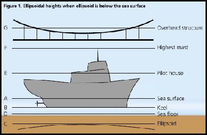
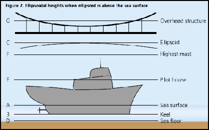
For safe sailing, two most important requirements are to be able to determine clearances between the sea floor and the keel of the ship, and between the mainmast and overhead structures, such as cables and bridges. For these clearances, the mariner has to know correctly and accurately the following:1. Location of the sea floor or ocean depth,2. Height of the overhead structure,3. Locations of the ship’s keel and mainmast. For centuries and even in the present practice, the above four surveyed positions are referenced to more than one datum. Further more, these datums are time-dependent and time-variant. We propose that the two clearances or the four positions are measured with respect to one time-invariant ellipsoidal surface as zero reference. Then, the mariners would have PHDthem correctly and accurately in one datum, whenever required. In shallow waters and inside harbors, the captain of a ship would be able to measure the clearances accurately and with confidence to avoid grounding or striking overhead obstructions, such as bridges and cables. Combining GPS surveys and acoustic soundings, highly accurate ellipsoidal depths of the sea floor can be established in new areas or by filling gaps independent of the stage of the tide and any tidal datum. In separate GPS surveys, the ellipsoidal heights for overhead structures can be determined. The time-invariant sea floor depths and heights of the overhead structures can then be stored in the Marine Information System (MIS) database for future use. While underway in shallow waters, in berthing, in approaching channels, and inside harbor, using a mainmast-mounted GPS antenna and the ship’s general arrangement drawings, the shipboard computer will determine the positions of the ship’s keel, mainmast, and Plimsoll marks. Then, recovering the already established sea floor depths and overhead heights, it can compute the two clearances for safe navigation without any reference to the time-variant tides, tidal datum(s), and ship’s draft. This article describes the surveying mode to establish time-invariant ellipsoidal depths or heights of the sea floor in the open ocean. A few additional survey procedures have been specified to achieve higher accuracy for shallow waters and inside harbors. A step by step algorithm is also included to compute the ship’s two vertical clearances. Surveying the sea floor and overhead structuresIn the marine scenario, the Ellipsoid of the World Geodetic System (WGS) 1984, the coordinate system used within GPS, is both below and above the sea surface, which can result in the surveyed ellipsoidal depths or heights to be plus or minus respectively. In the following figures, ellipsoidal depths or heights are positive upwards with respect to the ellipsoidal surface. A. When the WGS 84 Ellipsoid is below the sea surface – Figure 1 shows schematic locations for the overhead structure, ship’s mainmast, pilothouse deck, and keel, sea surface, sea floor, and ellipsoidal zero reference surface. AC = Ellipsoidal Height BC = Ellipsoid Height CE = Ellipsoidal Height CF = Ellipsoid Height CG = Ellipsoid Height BD = Depth of Sea Floor from keel as measured by acoustic sounding. During the GPS surveying, the distance BD between the ship’s keel and sea floor will be measured with presently used acoustic sounding techniques. Then, the ellipsoid height (h) of the sea floor DC will be DC = BC – BD = [CF – BF] – BD In this configuration, the distances CF, BF, and BD are measured during GPS surveys without any reference to the stage of the tide and/or tidal surface. This is the decided advantage over the depths determined with respect to time-variant tidal datums. In many cases, especially in deep water, the sea floor will be below the ellipsoid and have a negative height (-h). Here, the accuracy of the distance BD is accepted as achievable by acoustic techniques. B. When the WGS 84 Ellipsoid is above the sea surface – Figure 2 shows schematic locations when the ellipsoid is above the sea surface. DC = Ellipsoidal Height AC = Ellipsoidal Height BC = Ellipsoid Height CE = Ellipsoidal Height CF = Ellipsoid Height CG = Ellipsoid Height BD = Depth of Sea In this case, the ellipsoid depth of sea floor DC will be DC = – BC – BD = – [CF + BF] – BD. It may be pointed out that near Sri Lanka, the ellipsoid height of the sea surface AC has a maximum “low” of about -100 meters and this particular type of geometry is mostly not known to many users, particularly mariners. |
||||
Computing ship’s two clearances while underwayA. Clearance for ship’s keel – When the keel clearance (BD) is required, the mariner first surveys the geodetic position (f, ?, h) of the ship’s mainmast using GPS. Then, using the general arrangement drawings for the particular vessel, and combining with the ellipsoidal depth or height of the sea floor, the clearance can be computed (when ellipsoid is below sea floor) as BD = BC – DC = [BF – CF] – DC where BC is surveyed while underway and DC is taken from the database. Similarly the freeboard distance to the Plimsoll marks can be readily known. B. Clearance for ship’s mainmast – The clearance for the mainmast GF can be computed as GF = CG – CF where CF is surveyed with GPS while underway and CG is taken from the database. Ellipsoid depths and soundings accuracyIn open ocean areas, the accuracy of an ellipsoidal height (h) with GPS will be about ± 5 meters and thus the sea floor location with this order of accuracy will be suffi cient for most practical purposes. In shallow waters, along coastlines, and inside harbors, specially designed Differential GPS (DGPS) surveys can measure ellipsoidal heights in the range of ± 5-10 cm. The accuracy for keel clearance BD will be as per presently used acoustic soundings. To match the DGPS accuracy, it will be worthwhile that acoustic sounding techniques, procedures, and algorithms are examined again and updated as necessary. Special surveying for high accuracyIn congested areas, the accuracy of ellipsoidal heights and depths can be increased by surveying in DGPS mode. The following additional surveying procedures will help to improve the collected data for safer navigation, particularly to the traditional mariner: 1. In harbors, buoys with small DGPS receivers can monitor AC as it fl uctuates with the tide, to provide real-time data to the ship’s captain. Similarly the ship’s draft AD can be monitored with a keel-placed pressure sensor. 2. In cases where the sea fl oor heights vary signifi cantly from one time to another, it will require regular DGPS surveys to keep the mariner informed of shoaling and other shifts in the channels. 3. In case of small ships, DGPS surveys for roll, pitch, and yaw will improve the accuracy of the ellipsoidal heights of the keel and its clearance with the sea floor. ConclusionsGPS and DGPS surveys provide the accuracy necessary for the ellipsoidal depths and ship operations, whereby all measurements are referenced to the WGS 84 Ellipsoid. Thus, an invariant zero reference surface (or a vertical datum) will eliminate the necessity of measuring tides and ship’s draft, settlement(s), and squat during bathymetric surveying. In addition, this approach will replace any the time- variant tidal surfaces. The ellipsoid as the zero reference surface also allows the mariner, while underway, to determine keel and overhead obstruction clearance independent of the stage of the tide, and the draft of the ship and freeboard. As is traditional however, the prudent seaman will seek independent verifi cation of all the available nautical information. Copyright. We take the copyright for this geodetic approach in this manuscript. The authors would like to acknowledge that the paper was first published in GPS Word Sep 2005. |
|||||||||||||||||||||
|
|||||||||||||||||||||
|
Pages: 1 2


 (2 votes, average: 4.50 out of 5)


