| GNSS | |
Combined spatial-temporal filtering for interference mitigation in GNSS receivers
As an effective counter measure against GNSS interference, this paper presents a combined spatial-temporal fi lter for interference mitigation in an antenna-array GNSS receiver |
 |
|
 |
|
 |
|
Over the recent past, the vulnerability of Global Navigation Satellite Systems (GNSS) to interference has become a concerning issue (Mitch, 2011), (Pullen, 2012). Nowadays, illegal portable jamming devices are becoming popular to protect the user from being tracked by GNSS in their vehicle. These so-called personal privacy devices radiate different types of interference signals in the GNSS frequency bands and can make conventional receivers inoperable. Counter measures have to be taken to prevent strong interference from blocking the GNSS-receivers for safety critical applications.
A modular architecture concept for an array-antenna receiver is described in (Kappen, 2012). In this architecture a spatial filter at pre-correlation stage (i.e. before correlating the signal with the local satellite signal replica) is proposed for interference mitigation. As proposed in (Kappen, 2012), (Kurz, 2012) presents an implementation of a 2x2multi-antenna GNSS receiver architecture that features a sub-space based digital adaptive filter at pre-correlation stage. Based on the architecture in (Kurz, 2012), a recursive method for coefficient adaptation is presented in (Tasdemir, 2013), which leads to significant reductions in the computational complexity both in hardware and software.
The pre-correlation filters presented in (Kurz, 2012) and (Tasdemir, 2013) use only the spatial degrees of freedom for filtering interferences. The disadvantage of the spatial-only filtering is that the degrees of freedom are limited by the typically small number of antenna elements. That defines also the maximum number of interferers, which can be mitigated simultaneously. Furthermore, a spatial filter with limited degrees of freedom does not enable a sharp separation of the signal directions. Therefore, the mitigation of an interferer in the spatial domain also leads to the suppression of the satellite signals, if they have a direction close to the interferer’s direction.
As stated in (Rounds, 2004), spatial filtering can be combined with temporal filtering, in order to enhance the interference mitigation capability of an array-antenna receiver. In this paper, a combined spatial-temporal filter is presented in order to exploit the spatial, as well as, the temporal domain for interference mitigation. The filter consists of three stages: a notch filter (NF), a spatial filter and an equalizer filter (EQ). The NF at the first stage is realized as a bank of finite impulse response filters (FIR) and suppresses temporally correlated (narrowband) interference in the temporal domain. The spatial filter at the second stage is inherited from (Tasdemir, 2013) and suppresses wide band interference, which gets through the first stage. The last filter stage is required to reduce the negative side effects of the NF on the acquisition and tracking performance.

Notation: Throughout the paper, vectors and matrices are represented by bold roman letters. ||.|| stands for the Euclidean norm, (.)T for the transpose of a matrix, (.)H for the Hermitian transpose of a matrix, and (.)* for the elementwise conjugate. E{x(k)} is the mean value
![]()
of a sampled input argument x(k) computed at the time k . Ts over the last K samples. Ts is the sampling period.
Spatial filter
The block diagram of the adaptive spatial filter in (Tasdemir, 2013) is given in Figure 1. White blocks stand for computations with a processing equal to the sampling frequency. In (Kurz, 2012), these blocks are realized in dedicated hardware. Gray blocks stand for control oriented computations mapped to the embedded GNSS processor.
The input vector x(k) = [x1(k) … xN(k)]T of the spatial filter contains the digitized down-converted complex outputs of the antenna-array elements with N being the number of array elements. In the first step, x(k) is multiplied by an orthogonal matrix UH and is decomposed into N orthogonal signal channels y(k) = UH . x(k). Nint of these channels belong to the interference subspace, if Nint uncorrelated interference sources exist. (N – Nint) channels are interference-free and contain the noise and the GNSS signals “hidden” in the noise.
Decomposition is followed by the requantization step to reduce the wordlength of the signals. This is done in order to reduce the hardware complexity of the subsequent signal processing stages. In (Kurz, 2012), a wordlength of 2 bits is chosen for the filter output. In practice, this is a typical precision for the GNSS signals and does not lead to a significant loss of accuracy in the code delay estimation or in the user position estimation (Mezghani, 2010).
The re-quantization of the channels is carried out separately, i.e. the thresholds of the quantizers are individually adapted to the variance (power) E{|yn(k)|2} of the particular channel (n = 1, …, N). As a result, requantization equalizes the powers of the individual channels to each other. That means that after re-quantization, the power of the interference channels is suppressed to the level of the noise channels. After despreading (i.e. correlation with the locally generated satellite signals), GNSS signals are raised above the noise and the interference signals.
The decomposition matrix UH is derived from the auto-covariance matrix Rqq = E{q(k) . qH (k)} of the quantized filter output q. With V = diag (E{|y1,(k)|2}, …, E{|yN(k)|2}), UH = [u1 … uN]H is given by the eigendecomposition of the matrix V1/2 . Rqq . V1/2 and contains the eigenvectors un (n = 1, …, N). A computationally efficient method to adjust UH iteratively is described in (Tasdemir, 2013).
The last step of the spatial filter is the multiplication of the filter output vector q by U to transform q back to the original orthonormal basis (composition). In (Tasdemir, 2013), this step is shifted to the post-correlation stage. Composition is required, in order to compensate the carrier phase ambiguity induced by the decomposition step.
Temporal filter
In this section, a two-stage temporal filter is presented for interference mitigation at pre-correlation stage. The first stage of the filter is an adaptive NF that attenuates certain signal frequencies in order to remove narrowband interference. As a side effect, the NF generates echoes of the original satellite signal and can negatively influence the signal acquisition and the signal tracking performance at the postcorrelation stage. In order to reduce these side effects, an EQ filter is applied in the second stage of the temporal filter.
Notch filter
The adaptive NF in the first stage of the temporal filter is realized as an FIR-filter with M taps (Figure 2). The adaptation of the filter coefficients is based on the power minimization approach (Zoltowski, 1995). The complex tapweight vector b = [b0 … bM-1] of the filter is set to minimize the output power
![]()
subject to b0 =1. Since GNSS signals are well below the noise floor, the power minimization filter implicitly suppresses interference signals, while letting the noise and the satellite signals through.

After the interference mitigation, the filtered output y(k) is re-quantized to reduce its wordlength. If correctly adapted to the dynamic range of y, output of the quantizer can be modeled as
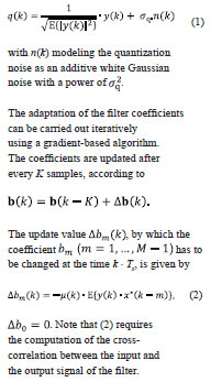
According to (Haykin, 1996), convergence of a gradient-based filter adaptation is guaranteed, if the step-size parameter satisfies /tap-input-power with
![]()
Therefore, the variance at the input of the filter is monitored, in order to adjust the step-size parameter inversely proportional to the input signal power, as shown in Figure 2.
Thus, the step-size parameter must be chosen proportional to the standard deviation of the filter output signal. This explains why the signal variance at the filter output is monitored in Figure 2 additional to the input variance.
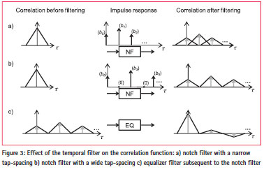
While suppressing interference signals, the NF generates echoes of the original satellite signal as a side effect. As a result of this side effect, time-shifted copies of the main correlation triangle appear in the correlation function of the filter output with the local satellite signal replica (Figure 3a). Similar to the echoes produced by satellite signal reflections (multipath), an overlap of the echo-triangles with the main triangle disrupts the satellite tracking loops. Therefore a tap-spacing > 2 . code- chip-duration is to be preferred, in order to avoid an overlap (Figure 3b).
Equalizer filter
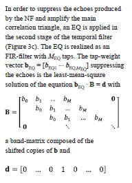
the desired combined response of the NF and the EQ. d indicates that all copies of the correlation triangles have to be zeroed but one. A gradient-based algorithm to find the solution iteratively is given by
![]()
![]() Since the tap-weight vector b of the NF is changed slowly by the gradient-based algorithm given in section of notch filter, few iterations of (3) are required after each update of b to adapt bEQ(k) to the updated value of b(k). In this paper, only one iteration (I=1) is carried out after each coefficient update period K . Ts.
Since the tap-weight vector b of the NF is changed slowly by the gradient-based algorithm given in section of notch filter, few iterations of (3) are required after each update of b to adapt bEQ(k) to the updated value of b(k). In this paper, only one iteration (I=1) is carried out after each coefficient update period K . Ts.
Combined filter
Figure 4 shows the spatial-temporal filter combining the spatial filter and the temporal filter. As in Figure 1, white blocks represent computations realized as dedicated hardware blocks, while gray blocks are tasks mapped to the embedded processor.
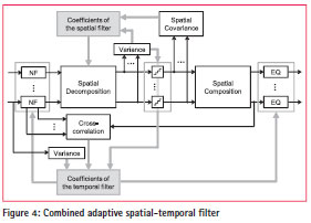
The first stage of the combined filter is a bank of N NFs to suppress temporally correlated interference. The NFs are followed by a spatial decomposition of the temporally filtered signal into its orthogonal spatial components.
Estimation of the spatial and the temporal filter coefficients is decoupled from each other. The spatial coefficients of the filter are derived from the spatial covariance matrix of the quantized output. If the filter coefficients are adapted correctly, narrowband interference is mitigated by the NFs and only wideband interference is detectable in the spatial covariance matrix. In other words, in the steady state the spatial filter ignores narrowband interferers. The coefficients of the NFs are determined based on the cross-correlation between the quantized filter output and the filter input signal. It is a justifiable assumption, that an interferer is received by all antenna elements and the same temporal interference characteristics can be observed for all antennas. Therefore, it is sufficient to compute the crosscorrelation for one antenna and use one common tap-weight vector for the NFs. Here, the composition step, which was shifted to the postcorrelation stage in (Tasdemir, 2013), is necessarily computed at the pre-correlation stage. Otherwise the carrier phase ambiguity induced by the decomposition step destroys the estimation of the temporal filter coefficients. Computation of the variance at the output of the NF (see Figure 2) can be left out, because the mean variance after decomposition is equal to the mean variance before decomposition.
Simulations showed that the interference mitigation performance of the combined filter was improved if the tap-weight vector b of the NFs was normalized by its Euclidean norm after each coefficient update. However, if b is normalized, it does not converge back to the default vector b0 = [1 0 … 0], after interference signals disappear. Since the EQ realized as an FIR is not capable of perfectly suppressing the echoes for all possible values of b, the “normalized power minimization algorithm” may slightly degrade the SNR in the absence of interference. In order to avoid an unnecessary generation of echoes in the absence of interference, b needs to be slowly forced towards b0, if the temporal filter does not detect and suppress any temporally correlated interference. This can be detected by comparing the input power and the output power of the notch filters.
Simulation results
In this section, the benefits of the combined spatial-temporal filter over the spatial-only filter are discussed based on MATLABsimulations. A single-antenna receiver (1-ant), a 2×2-array-antenna receiver with spatial-only filtering (2×2-ant + sf), and a 2×2 array-antenna receiver with spatial-temporal filtering (2x2ant sf + tf) are simulated. The element spacing of the array-antennas are λ/2. Antenna-signals are down-converted to the baseband and sampled at a rate of 2.047 MHz before interference mitigation. The NF and the EQ of spatial-temporal filter have M = MEQ = 5 taps with a tap-spacing of 5 samples. Averaging time is 1 ms, i.e. the averaging is done over K = 2047 samples. SNR of the received satellite signal (GPS PRN 1) before correlation is -16 dB. A blind adaptive beamformer is applied at the post-correlation stage to form a beam towards the satellite and maximize the SNR (Kurz, 2012).
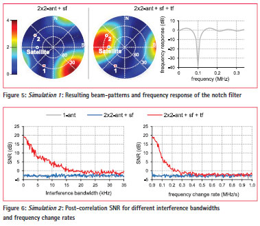
Simulation 1 examines an interference scenario with two interference sources, in order to demonstrate the differences between the spatial-only and the combined spatial-temporal filtering. Interferer 1 is a wideband interferer (two-sided bandwidth = sampling rate) with an interference-to-signal-ratio (ISR) of 50 dB. Interferer 2 is a continuous-wave (CW) interferer (bandwidth = 0, frequency = fL1 + 100 kHZ) with an ISR of 45 dB. Figure 5 shows the combined beampatterns of the pre-correlation filtering and the post-correlation beam-forming. As can be seen from the corresponding beam-pattern, the spatial-only filter is forced to attenuate two distinct signal directions, in order to mitigate the interference. As a result, the beam, which should be focused towards the satellite in the interference-free case, is strongly shifted away from satellite direction. In contrast to the spatial-only filter, the combined filter mitigates CW-interference in the temporal domain. The frequency response of the NF is shown in Figure 5 (right), for this case. In total, one spatial degree of freedom is used because of the wideband interference and the post-correlation beam-former is able to form a beam approximately to the satellite direction. Compared to the spatial-only filtering, the combined filter increases the SNR at the postcorrelation stage by 6.14 dB.
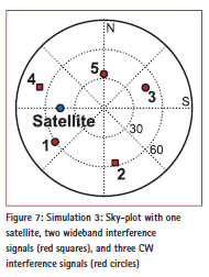
Simulation 2 analyzes the behavior of the combined filter for growing interference bandwidths or for changing frequencies. The frequency of a narrowband can change due to an acceleration of the receiver relative to the interference source. In the simulation, an interferer (ISR = 50 dB, center frequency = fL1 + 150 kHZ) radiates from the same direction as the satellite. In this case, the mitigation of the interference signal in the spatial domain also cancels the satellite signal. The estimate of the post-correlation SNR over the interference bandwidth and the frequency change rate is shown in Figure 6. While a CWsignal can perfectly be mitigated in the temporal domain, performance of the temporal filter decreases for growing interference bandwidths and for growing frequency change rates.
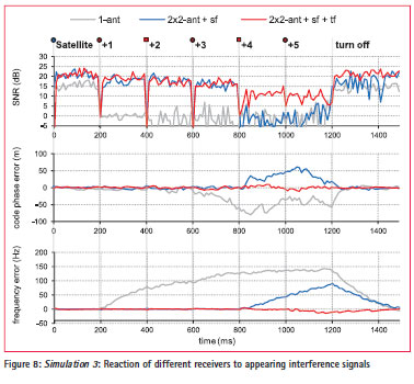
Simulation 3 demonstrates the improvement of the combined filter over the spatial-only filter for the case where the number of the interference sources exceeds the N-1 spatial degrees of freedom. The directions of the satellite and the interferers are given in Figure 7. All interferers have an ISR of 50 dB. Interferers 1, 3, and 5 radiate CW-signals with distinguishable frequencies (fL1 -50 kHZ, fL1 + 250kHZ, fL1 + 550kHZ); interferers 2 and 4 radiate wideband signals.
Starting without the interferers, an interferer is turned on after every 200 ms. At the time of 1200 ms, all interferers are turned off again. Estimate of the post-correlation SNR, the code phase error, and the frequency error of the signal tracking loops are plotted over time in Figure 8. It can be identified that the spatial-only filter is overextended, if the number of interference sources exceeds (N-1). In this case, the SNR drops abruptly and the tracking loops start to drift away from the satellite signal. Especially, the carrier tracking loop is intensely affected and “deceived” by the unsuppressed CW-interference.
Conclusion
This paper presents a combined spatialtemporal filter for interference mitigation in an antenna-array GNSS receiver. The filter is based on the spatial filter introduced in (Tasdemir, 2013) and extends this by a bank of adaptive FIR-filters in the front. These are used as notch filters and take over the mitigation of narrowband interference by attenuating certain frequencies in the frequency spectrum of the input signal. The adaptation to the interference situation follows a gradient-based power minimization method. As a result of adding temporal degrees of freedom to the spatial filter, the filter capacity in the spatial domain is preserved for the mitigation of wideband interference. Undesired side effects of the notch filters on the satellite signal tracking are diagnosed and minimized by adding an adaptive equalizer filter subsequent to the interference mitigation.
Functionality of the filter is verified by simulations using synthetic data. As expected, the benefit of the combined filter approach becomes evident mainly in two cases. 1) If an interference source has a signal direction close to a satellites direction, the satellite signal is also intensely affected by the interference mitigation in the spatial domain. While the spatial-only filter does not distinguish between different types of interference, the combined spatial-temporal filter can rescue the satellite signal from narrowband interference. 2) Significant improvements of the combined filter over the spatialonly filter can also be observed, in case the number of interference directions exceeds the number of spatial degrees of freedom. This case is not unrealistic, since its occurrence does not require the existence of a high number of interfering devices but can also be caused by reflections of one interfering signal. While spatial-only filtering is defenseless in such a situation, the combined-filter provides an improved protection against interference by exploiting temporal characteristics of the interference.
Acknowledgements
This work was funded by the Space Administration of the German Aerospace Center (DLR) on behalf of the Federal Ministry of Economics and Technology based on a decision of the German Federal Parliament reference no. 50 NA 1111.
References
S. Haykin (1996). “Adaptive Filter Theory”, 3rd Edition, Prentice-Hall, 1996.
A. Mezghani, F. Antreich, J. A. Nossek (2010). “Multiple Parameter Estimation with Quantized Channel Output”, WSA 2010, Bremen, Germany, 23-24 Feb 2010
R. H. Mitch, R. C. Dougherty, M. L. Psiaki, S. P. Powell, and B. W. O’Hanlon (2011). “Signal characteristics of civil GPS jammers”, ION GNSS 2011, Portland, Oregon, 19–23 Sep 2011
G. Kappen, C. Haettich, M. Meurer (2012). “Towards a Robust Multi- Antenna Mass Market GNSS Receiver”, PLANS 2012, Myrtle Beach, South Carolina, 23-26 Apr 2012
L. Kurz, E. Tasdemir, D. Bornkessel, G. Kappen, F. Antreich, and M. Sgammini (2012). “An Architecture for Embedded Antenna-Array Digital GNSS Receiver Using Subspace-Based Methods for Spatial Filtering”, NAVITEC 2012, Noordwijk, The Netherlands, 5-7 Dec 2012
S. Pullen and G. Gao (2012). “GNSS Jamming in the Name of Privacy”, Inside GNSS Magazine 7(2) S. Rounds (2004). “Jamming Protection of GPS Receivers”, GPS World 15(2)
E. Tasdemir, L. Kurz, and T. G. Noll (2013). “Optimization of a Blind Adaptive Spatial Filter for Interference Mitigation in GNSS Receivers”, ION GNSS 2013, Nashville, Tennessee, 16-20 Sep 2013
M. D. Zoltowski and A. S. Gecan (1995). “Advanced Adaptive Null Steering Concepts for GPS” MILCOM 1995, San Diego, California, 5-8 Nov 1995.
The paper was presented in ENC-GNSS 2014, Rotterdam, Netherlands, 15-17 April.


 (7 votes, average: 4.71 out of 5)


Leave your response!