| Positioning | |
The benefits of three frequencies for high accuracy positioning
|
|||||||||||||||||||||||||||||||||||||||||||||||
|
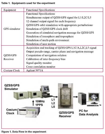
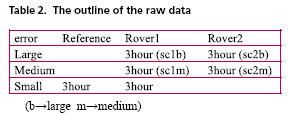
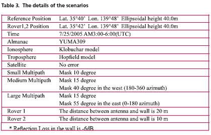
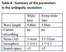
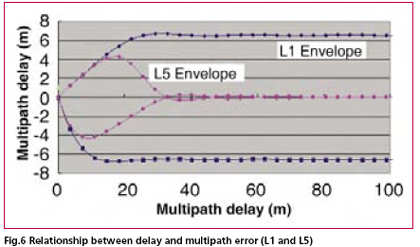
GPS modernization will expand the area of positioning service and will increase its convenience. Particularly, the third civil frequency namely L5, which will be provided by both modernized GPS and QZSS, is expected to improve the performance of precise positioning using carrier phase observation. This paper reports an experimental result regarding the convenience of additional L5 signal. Actual navigation signals generated from GPS simulator were received by triple frequency GPS receiver in the experiment. Navigation data, pseudo-range and carrier phase observation have been obtained and used for the analysis. This experiment verifies the improvement of ambiguity fixing time and multi-path mitigation using three frequency signals. ExperimentConfiguration of equipmentsA GPS simulator designed for the modernized three GPS signals and a GPS/ QZSS receiver developed for the high accuracy positioning experiment were used for this experiment. These equipments have been developed by Japan Aerospace Exploration Agency (JAXA) as a part of QZSS navigation test bed. Equipments used for this experiment are listed in table 1 with their specifications. Figure 1 shows the data flow of this experiment. A cesium clock was employed to provide stable external reference for GPS simulator in order to generate GPS-like high quality navigation signals. The data analysis software was developed by Tokyo University of Marine and Science Technology. DGPS and RTK solution as well as usual navigation solution can be obtained with this software. It is also possible to evaluate important parameters for precise positioning such as ambiguity fix rate using this software. Data generation by the simulator and the data recording by the receiver have been performed in real time while data analysis was performed off-line. Scenarios for data acquisitionThe possibility of the high accuracy positioning with triple frequencies was investigated by using pseudo-range and carrier phase measurements. The base-line between reference station and rover station is set about 3.7km because we want to assume that the effects of the atmosphere can be disregarded. Particularly, the effect of L5 frequency in the ambiguity resolution was investigated in the specular multipath condition. The algorithm used in this test is general code and carrier DGPS using double difference. Table 2 shows the details of the data. Table 3 also shows the details of the scenarios. All of the parameters were set GPS simulator. The reason why there are two rovers is to analyze the case of the different multipath delay. Since the band of L5 frequency has high chip rate compared with L1 frequency, the improvement in accuracy is expected in the case that the multipath delay is over 20 m. Figure 2 shows the configuration between the antenna and the wall in the case of medium and large multipath error respectively. Algorithm of precise positioningPositioning algorithm to analyze observation data is described in this section. The overall flow of analysis is as follows. 1) Read observation data from reference and rover station 2) Cycle slip detection 3) Calculation of satellite position 4) DGPS and RTK DGPS was carried out respectively by using L1 pseudo-range and L5 pseudorange. RTK was carried out by using general double difference data. Since there are triple frequency observation data, ambiguity resolution was carried out by using the combination of L1- L2 (wide-lane) and L2-L5 (extrawide- lane). The reason why we choose these combinations is that the noise level is not so large and the effect of ionosphere is same order compared with L1. Although this linear combination technique in order to resolve ambiguities is not the best way, the object in this paper is to analyze the effects of the three frequencies in the multipath condition. So the conventional method in order to resolve ambiguities is used in this paper. Ambiguity resolution was initialized when the cycle slip was detected in each frequency. In this experiment, cycle slip due to the band of L2 was The flow of ambiguity resolution algorithm is as follows. 1) DGPS position estimate using non smoothed pseudo-range 2) Initial estimate of the ambiguity 3) Ambiguity search (position estimate using all ambiguity candidates) 4) Rejection of candidates due to criteria in both measurements and positioning domains (statistical test) 5) After the one candidate is retained, receiver position is computed with each ambiguity candidate The algorithm for wide-lane is same as the algorithm for extra-wide-lane. Table 4 shows the summary of the parameters in the ambiguity resolution. Experimental ResultsThe experimental results are shown in the following sections. DGPS positioning resultsFig.3-Fig.5 shows the horizontal positioning error of the base-line between the rover and the reference station for three different multi-path scenarios. Each figure contains the errors for both L1 and L5 DGPS results. In case of no multipath environment, the horizontal positioning error is less than 1 m. Both Fig.3 and Fig.4 are the experimental results for scenarios in which the distance between the antenna and the wall is 20 m. Although the distance between the antenna and the wall is identical in both cases, the difference of obstruction condition makes a significantly different result. The positioning error for scenario sc1m is smaller than that of scenario sc1b since the obstruction condition for the latter is worse than the former. However, if we employ L5 measurements, the accuracy degradation was improved by 50% or more (Fig.3 and Fig.4). The Fig.3 and Fig.5 are the result of the same obstruction condition. The difference of the both figures is based on the different distance of an antenna and a wall. In Fig.3, a reflected signal is delayed 20 to 30 m. On the other hand, the delay of reflected signal is within 20 m in Fig.5. Therefore, even if we used L5 signal, which chip rate is high, the multipath errors couldn’t be reduced in scenario sc2b. And all results of positioning error in multipath environment are significantly worse than that of usual DGPS with no multipath environment. For comparison, the relationship between the delay of reflected signal and the multipath error is shown in Fig.6 (reflection loss is -6dB), where the receiver bandwidth is 20 MHz. In these experiments, a GPS receiver equivalent to 0.1 chip narrow correlator was used. Positioning results using carrier phaseIn this section, we show the positioning results using carrier phase observation for both latitude and longitude error components of baseline vector between the reference station and the rover in two scenarios (sc1b and sc2m). Fig.7 and Fig.8 are the results for scenario sc1b, which are obtained by wide-lane (WL) and extrawide- lane (EWL), respectively. In the ambiguity resolution, WL utilizes the L1 DGPS positioning result for ambiguity search and EWL utilizes the L5 DGPS positioning result. Fig.7-Fig10 shows that the experimental results using L5 signal are slightly noisier. But the ambiguity fixing success rate is very high in L5 case evidently. In this paper, WL ambiguity resolution based on the EWL was not carried out. However, it will be easy for us to improve the success rate by using the results of EWL in the WL ambiguity resolution. Moreover, in case of using EWL, the most of ambiguity resolution were determined at 1 epoch. These results mean that L5 signal is really effective for a precise positioning, especially in the urban area. Table 5 shows the number of successful ambiguity fix and its success rate, for both WL and EWL, respectively. In this table, the right side number shows the number of times with five or more visible satellites. Based on this table, in case of scenario sc1b, in which multipath effect is large, the ambiguity fixing success rate is only 25% and even in case of scenario sc2m, in which mutlipath effect is medium, that rate is 69%. On the other hand, when using EWL, the rate of that is 95% or more. Therefore, it is confirmed that EWL in ambiguity resolution is effective. ConclusionThis paper introduced the effectiveness of new L5 frequency for precise positioning based on the experiment using three frequency GPS simulator and three frequency QZSS/GPS proto-type receiver. Data analysis result shows that the new L5 signal contributes to the improvement of positioning accuracy for DGPS and RTK under the severe multipath environment. It is also verified that the ambiguity fix rate of RTK is significantly improved. AcknowledgementAuthors wish to acknowledge the contributions provided by Furuno Electric to this study. ReferencesNobuaki Kubo, Akio Yasuda, Isao Kawano, Takeshi Ono, Chie Uratani. “The Benefits of Three Frequencies for the High Accuracy Positioning”, 49th Space Sciences and Technology Conference, Nov. 2005 Yun Zhang, Nobuaki Kubo, Akio Yasuda. “The Benefit from Triple Frequencies in Ambiguity Resolution, The Journal of Japan Institute of Navigation”, Vol.112 pp219-227. March 2005 HAN, S., RIZOS, C., “The impact of two additional civilian GPS frequencies on ambiguity resolution strategies”, National Meeting U.S. Institute of Navigation, “Navigational Technology for the 21st Century”, Cambridge, Massachusetts, 28-30 June, 315- 321. 1999 Isao Kawano, Masaaki Mokuno, Satoshi Kogure, Motohisa Kishimoto. “Japanese Experimental GPS Augmentation using Quazi- Zenith Satellite System (QZSS)”, ION-GPS-2004, Sep. 2004 Takeshi Ono, Isao Kawano, Satoshi Kogure. “Test Bed for Satellite-based Positioning System using Quasi-Zenith- Satellites”, GNSS-2004, Dec. 2004 Satoshi Kogure, Isao Kawano, Motohisa Kishimoto, et. al., “3D Simulation for the Improvement of GPS Performance by Quasi-Zenith satellite system”, 24th ISTS, June 2004 Takeshi Ono, Isao Kawano, Satoshi Kogure, Motohisa Kishimoto,Yousuke Yamamoto “GPS and QZSS Preliminary Interoperability Study”, |
|||||||||||||||||||||||||||||||||||||||||||||||
|
|||||||||||||||||||||||||||||||||||||||||||||||
|




 (No Ratings Yet)


