| GNSS | |
Enhancement of 3D monitoring networks’ sensitivity by low cost innovative implementation
The special Portable Metallic Pillar (PMP) that is presented can be used for marking accessible points |
 |
|
 |
|
Monitoring is the fastest growing discipline in the survey market. Surveyors undertake the difficult task to answer: What is moving? How fast? In what direction? Is it accelerating? The answers come from reliable, precise measurements from this modern instrumentation (Brooks O. (2011).
Also structural health monitoring is one of the important components in the maintenance technology for civil infrastructures (Hongwei L., Jinping O. (2006)).
For these reasons monitoring sensors’ networks were established all around of bridges, tunnels, dams, railways, nuclear power stations, high buildings and cultural heritage monuments in order to collect any spatial and qualitative information concerning the specific constructions (Nicaise Q., Cranenbroeck J. ( 2015)).
All these constructions benefit from implementing monitoring systems. Such systems are expected to provide multi-dimensional alarms, visualization of results in near-real time, and millimeter accuracies. (Danisch, L. et al (2008)), (Wilkins R. et al (2003)).
Thus the data are acquired continuously and are sent to central servers to be elaborate, to be adjusted and to extract the results (Singer J. et al (2009)).
3D geodetic monitoring networks and instrumentation as total station, GNSS receivers, retrorefiectors ect., consist part of these sensors collecting spatial information for the health of the construction.
A main parameter is the monitoring network’s sensitivity, which was defined as the minimum displacement that could be detected by a network for a concrete confidence level (usually 95%). To be more specific if it is needed to detect displacements of ±5mm for confidence level 95%, generally the points coordinates ought to have rms about ±2mm.
In most cases, accuracy of the order of ±1mm is required (Delikaraoglou D. et al, 2010), (Lambrou E. et al (2011)), (Pantazis G. (2015)), (Chounta I., Ioannidis Ch. (2012)), (Huang T., et al (2010)). Today the evolution of the technology provides the possibility of accurate geodetic measurements. The modern total stations adjust automatically and electronically in real-time the errors of the line of sight, of the tilt axis, of the z and Hz compensator, of the V-index and of the ATR collimation if it is available (Uren J., Price B. (2010)).
Thus the displayed measurements are free of them and considerable accuracy is provided for angle and distance measurements reaching the ±0.5” and ±0.2mm correspondingly. Also the embedded compensator ensures their accurate levelling. (Lemmon T., Jung R. (2005)) (Zogg H., et al (2009))
Nevertheless the measurement errors that still remain are:
• the centering error of both instrument and targets
• The error in the measurement of both heights of instrument and targets.
These errors are signiflcant and surcharge the measurements and the calculated coordinates with remarkable inaccuracies (Lambrou E. (2013)), (Doukas J. (1984)), (Lambrou E. et al, (2011)), (Nikolitsas K., Lambrou E. (2015)).
This paper aims to propose techniques in order to clear or eliminate these errors.
Usually the monitoring networks are implemented by permanent instrumentation which is established at permanent positions namely cement pillars, metallic arms or other permanent constructions. In these cases the centering and levelling error of the instrumentation are totally removed as all the measurement phases are referred to the initial point where the instrument was set and levelled.
This instrumentation consists of tens or hundreds of Total Stations (TS), or GNSS receivers and thousands of retroreflectors and other sensors. (http:// www.ipcmonitoring.com/portfolio/ the-London-crossrail-project)
It is obvious that such a permanent 3D network is of high cost which isn’t always feasible to afford. Additionally cement pillars, metallic arms or other permanent constructions which are appropriate for the instrumentation set up aren’t always allowed to be established at every site such as the archaeological ones. (Telioni E., Georgopoulos G. (2006)), Georgopoulos G., Telioni E. ((2008)).
So there are cases where the permanent establishment of this instrumentation is banned for cost reasons or for environmental circumstances or for another special status quo.
Thus the main goal is to devise an innovate fabrication for the implementation of high precision 3D networks, not permanent, with low cost and without any visible interference to the environment. Additionally this implementation should ensure the force centering and the proper levelling of the instrumentation in order to erase the above mentioned fundamental errors. The successful results of the use of the Portable Metallic Pillars (PMP), in two sensitive 3D monitoring networks, support the above statement. The PMP permits the establishment of high sensitivity networks with minimum cost. Additionally PMP allows the quick instrumentation set up, so it eliminates the time for the network measurement.
Outline of the Portable Metallic Pillar (PMP)
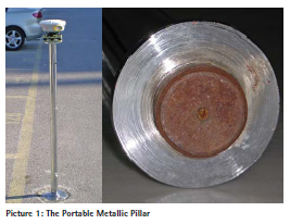
The PMP (picture 1) is composed by two separate parts: The pole and the ground – base.
The pole is a cylinder, which was made by nickel-plated heavy duty steel in order to be protected of the corrosion. It has length 118cm, diameter 5cm and it weights about 8Kgr. The length of the pole should be such as to not be oscillated during the measurements. Also, an observer of medium height must be able to use it and the line of sight of the instrument must overcome common obstacles as cars, motorcycles, etc.
The top of the pole is a flat circular disk of 12cm diameter and 7mm width. It has a projected screw at the center in order to put on the tribraches at a unique position. The center of this screw defines the network’s point.
The bottom of the pole has also a flat circular disc and the projected part of its body is formed so as to be also a screw (picture 1) in order to screw in the ground – base accurately at a unique position.
The manufacture of the poles should satisfy the following requirements in order to be used at every network’s point:
– the poles must have the same length (The distance between the top and the bottom circular disks).
– The center of the top screw and the center of the bottom screw must belong to the axis of the pole (cylinder). Also the axis of the pole must be perpendicular to both circular disks (top and bottom bases of the cylinder) (Lambrou E. et al (2011)).
– Each pole must be screw exactly by the same way on every ground – base.
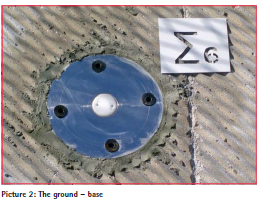
The ground – base is circular with 20 cm diameter and 2cm thickness; it has a hole with turns of screw in the center of 5cm diameter where the pole screws (picture 2). Also it has four holes at the circumference where special porps are put to firm it in the ground. The base was made by inox in order to protect it from rusting. A pole costs about 250 euros as 300 euros are enough for the ground – base.
Implementation of Portable Metallic Pillar (PMP)
The ground base is incorporated in the ground at the selected position. It is stabilized by concrete. Special attention must be paid for the proper levelling of the ground-base. The ground base should be horizontal in order to force the pole to stand at vertical position when it is screwed on the ground base. This could be realized by using a digital level during the establishment procedure.
As long as the pole is screwed on a ground base and a tribrach is also screwed and leveled on the top of the pole so a TS or a GNSS receiver or a retroreflector could be put accurately at the same position at every measurement campaign. Thus the centering error is totally removed. When a measurement campaign finish, the poles are put off from the ground bases. Nothing remains at the site except the embedded bases in the ground.
It is obvious that the base will permanently remains at the ground position as it is almost impossible to be removed. Thus the number of the ground bases which are needed is equal to the number of the network’s control points. On the contrary, the poles are mobile. So any pole can be put on every ground base as they are exactly suchlike to each other. Therefore the same poles can be used in several of such networks. So, in order to eliminate the total cost, the manufacture of so many poles as ground–bases does not need.
Accurate measurement of instrument height (IH)
The measurement of the height of TS, targets and GNSS antenna is the second significant error. The following methodology ensures accuracy of ±0.1mm to ±0.2mm for instruments height measurement. A digital level and a rod are required in order to apply the procedure.
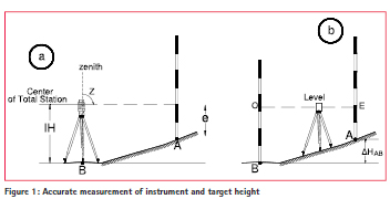
On a point A, which is situated close to the TS’s station B, about 5-6m, the rod is put. The reading e on the rod is taken by the TS, under the presupposition that the line of sight is horizontal (namely z=100g). Two readings are taken in 1st (eI) and 2nd (eII) telescope position (namely z= 300g) (Figure 1a). The mean value is calculated as

As the level’s reading accuracy on a digital rod is ±0.1mm. The total accuracy succeeded depends on the observer’s reading skill on the rod (e), that could be ± 0.2 mm.
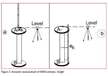
A simpler procedure is applied for the accurate measurement of a GNSS antenna height. The level is put close to the network point. The rod is put firstly on the surface where the antenna’s bottom is seated where a reading eA is taken (Figure2a). Afterwards the rod is put on the surface where the height of the point should be referred (i.e. the bottom of the pillar) where a reading eB is taken (Figure2b).
The antenna’s height comes out as
![]()
Where FCH (Face Center Height) is the distance from the antenna’s bottom to the antenna’s face center (is given by the manufacturer). The total accuracy succeeded is of the order of ±0.1mm.
Applications by using PMPs
“Karaiskaki” football stadium
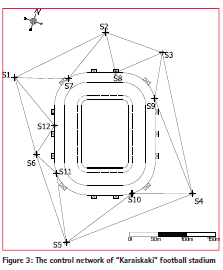
The “Karaiskaki” football stadium, of a capacity of 32000 people, was constructed on a very unstable area close to the sea. The stadium was built on 2004, in order to support the Athens Olympic Games. For monitoring the behaviour of the structure, a 3D control network, which consists of twelve points, was established at the surround area of the stadium (Figure 3). (Bisbilis K. (2007)). The six accessible points of the network were implemented by using PMPs. The rest six inaccessible points were put on the supporting body of the stadium. These points were also marked permanently by small circular targets. The distances between the points fluctuate from 45m to 220m.
The network was measured three times, December 2006, May 2007 and March 2010. In the two campaigns (December 2006, May 2007) the total station Topcon GTS 3003 was used for the measurements, which provide accuracy ±9cc for the direction and ±2mm ±3ppm for the distance measurements. In the third campaign (March 2010) the total station Leica TCRM 1201+ was used, which provide accuracy ±3cc for the direction and ±1mm±2ppm for the distance measurements.
It is remarkable that the time needed for the measurements from each station was maximum 20 minutes, namely 2 hours were totally needed. This was achieved as the PMPs facilitate the placing and the levelling of both instrument and targets.
The adjustment of the network was carried out in an arbitrary local reference system.
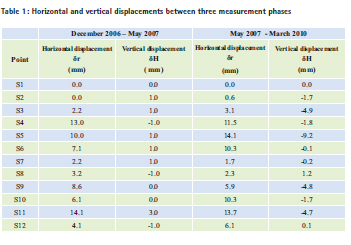
The mean rms of the determined coordinates x, y, z is of the order of ±3mm. That means that displacements less than 1cm can be detected for confidence level 95%. Table 1 presents the points displacements between three measurement periods. The time period December 2006 – May 2007 there aren’t vertical displacements but there are horizontal ones at the points S4, S5, S9, and S11. The next period May 2007 – March 2010, almost 3 years, later, there is a vertical displacement at the point S5 as well as horizontal displacements occurred at the points S4, S5, S6, S10 and S11.
The church of Megali Panayia in Samarina
Samarina, reportedly the highest village in Greece, at an elevation of some 1450 m, is situated on the wooded slopes of Mount Smolikas in the Pindos Mountains, approximately 70 km west of Grevena in northwestern Greece. Samarina’s post Byzantine church of Megali Panayia (Great St. Mary’s church) has been built in 1816 and is the area’s main religious landmark, as well as a wonder of nature. The church is famous for its painted ceilings, frescoes, and a finely carved iconostasis (templon), but also that the roof of the altar, covering the apse, in the east side of the 40m long building, “accommodates” a big pine tree with no sight of the tree’s roots to be found within the church or outside the wall (picture 3).
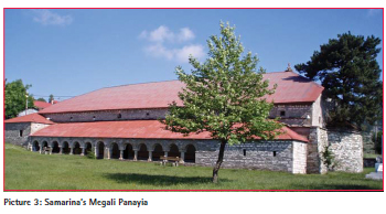
The church is constructed of local stone and has very shallow foundations sitting on unfavorable ground, composed mainly of clay, silt and peat, with the solid rock found in depths of more than 15 m from the surface (Delikaraoglou, et al (2010)).
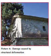
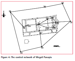
As the church suffered from extensive structural deformations systematic monitoring should be started. The establishment of permanent concrete pillars was forbidden as it would destroy the sight of the monument. Additionally the accuracy of the network’s points was to be at the level of a 1-2mm in order to detect every displacement up to 5mm for confidence level 95%.That means a high sensitivity network. (Delikaraoglou, et al (2010)), (Georgopoulos, et al (2010)). A main 3D network was established inside and outside the monument, which consists of 15 station points. Six of them are located outside of the church and nine more in the interior (figure 4). Also many points were put on the church’s body namely on the walls. These points are implemented by special self-adhesive retroreflectors.
The external six points, with inter-station distances ranging from about 19 to 69m, were implemented by using PMPs.
The network was measured four times, in intervals of about 45 days, June 2009, July 2009 September 2009 and October 2009. In all campaigns the total station Leica DTM 5000 was used which provide accuracy ±1.5cc for the direction and ±0.5mm±1ppm for the distance measurements. (http://www. leicageosystems. com/media/ new/product solution/L3_TDA5005.pdf)
The measurements from the six PMPs were carried out in about 4 hours ensuring the simultaneously of the procedure providing time efficiency. The network adjustment was carried out in an arbitrary local reference system. The point S2 was considered stable as was placed at more stable ground. However its stability was checked by an external network of the wide area.
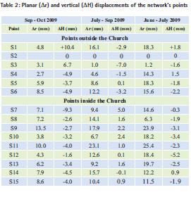
Thanks to PMPs the total accuracy of the determined coordinates x, y, z is of the order of ±0.2mm. That means that even displacements of the order of 1mm could be detected. As it is presented in table 2 almost all the points have horizontal and vertical displacements.
Conclusions
As nowadays the number and the requirements for 3D monitoring networks are augmented the proposal of low cost and high sensitivity network seems to be attractive. The two erroneous crucial parameters that still remain at the geodetic measurements, namely the centering error and the measurement of the instrument height, cause significant uncertainties to the results of the impermanent 3D monitoring networks.
A prototype way for the implementation of network’s points is being implied which ensures precise centering for the instrumentation. The special Portable Metallic Pillar (PMP) that is presented can be used for marking accessible points. The PMP provides forced unique instrument’s centering less than ±0.1mm. It is light enough to carry, it accelerates and facilitates the centering and levelling of the instrumentation as well as it eliminates the time needed for the measurements.
Additionally PMP is environment – friendly as it is invisible but for ever permanent.
Additionally two simple procedures for the measurement of both TS’s and GNSS antenna’s height are presented, which provides accuracy of ±0.2mm and ±0.1mm correspondingly. This permits the total 3D network solution to be achieved at the same order of the rms for x, y and z coordinates.
Both applications were proved to be successful. The PMPs use provides exceptional accuracy ±0.2mm at the Megali Panayia network where a first order TS was used. Also the duration of measurements was fairly shortened.
At the “Karaiskaki” football stadium PMPs allow for super quick measurements which are needed for this application and satisfled accuracy according to the used TS.
Consequently the use of the PMPs it is recommended for the implementation of monitoring networks. Also if they combined with the accurate instrument height determination, provide low manufacturing cost, easy establishment, no environment intervention, quick instrument setting and measurement acquisition and finally high coordinates’ accuracy. Thus they allow the high sensitivity 3D network achievement in order to detect displacements of the order of 1mm.
References
Bisbilis K. (2007). Monitoring of the displacements of the new Karaiskaki football stadium. Establishment of a vertical control network at the surround area. Unpublished diploma dissertation (in Greek), NTUA, School of Rural and Surveying Engineering, Athens.
Brooks O. (2011). Modern Surveying. Monitoring Progress. www. GEOconnexion.com /.May/June 2011.
Chounta I., Ioannidis Ch. (2012) High Accuracy Deformation Monitoring of a Concrete Beam using Automatic Photogrammetric Techniques FIG Working Week 2012, Italy
Georgopoulos A., Ioannidis Ch., Delikaraoglou D., Lambrou E., Pantazis G.(2010). Technical report of research project Investigation of methods for the implementation of a monitoring network and the 3D presentation of the displacements of Samarina’s post Byzantine church of Megali Panayia at Grevena in northwestern Greece
“ Delikaraoglou D., Georgopoulos A., Ioannidis Ch., Lambrou E., Pantazis G. (2010). Using geodetic and laser scanner measurements for measuring and monitoring the structural damage of a post-byzantine church. “8th International Symposium on the Conservation of Monuments in the Mediterranean Basin. Monument Damage Hazards & Rehabilitation Technologies”, Patra, Greece
Danisch L., Chrzanowski A., Bond J., Bazanowski M. (2008) Fusion of geodetic and MEMS sensors for integrated monitoring and analysis of deformations, 13th FIG Symposium on Deformation measurements and Analysis – Measuring the changes – 4th IAG symposium on
Geodesy for Geotechnical and Structural Engineering”, Lisbon, Portugal Doukas, J. (1984). The effect of the centering error in the adjustment of an horizontal trigonometric network. Thessalonica: GYS Georgopoulos G. Telioni E., (2008) Estimation of the vertical deformations of the stylobate of ancient temples – The case of Theseion, 13th FIG Symposium on Deformation measurements and Analysis – Measuring the changes – 4th IAG symposium on Geodesy for Geotechnical and Structural Engineering”, Lisbon, Portugal
Hongwei L., Jinping O. (2006) A remote deformation monitoring system for a cable-stayed bridge using wireless internet-based GPS technology. 3rd IAG / 12th FIG Symposium, Baden, Austria Huang T., Li G., Chen H., Jiang M., (2010), Precise Control Survey for Erecting the Steel Pylons of the Third Nanjing Yangtze River Bridge, China: Case Study, Journal of Surveying Engineering, Vol. 136, Issue 1, pp.29-35 Lambrou E. (2013) Analysis of the errors of the antenna’s set up at the GNSS measurements. Journal of Civil engineering and Architecture (ISSN 1934-7359) Volume 7, No. 10 (Serial No. 71), pp. 1279-1286
Lambrou E., Nikolitsas K., Pantazis G. (2011) Special marking of 3d networks’ points for the monitoring of modern constructions. Journal of Civil engineering and Architecture (ISSN 1934-7359), Volume 5, Number 7, Serial No 44, pp 643-649.
Lemmon T., Jung R. (2005) Trimble S6 with magdrive servo technology, white paper, Trimble Survey, Westminister, Colorado, USA http://www.trimble.com/globalTRLTAB. asp?nav=Collection-30453 Last access 9/2015
Nicaise Q., Cranenbroeck J. (2015) Talk to the Bridge: A New Approach in Structural Health Monitoring Based on the Internet of Things. FIG Working Week 2015, Sofia, Bulgaria
Nikolitsas K., Lambrou E. (2015) Detecting the centering error of the geodetic instrumentation, Journal of Surveying Engineering under review Pantazis G., (2015) complete processing methodology for 3D monitoring using GNSS receivers. FIG Working Week 2015, Sofia, Bulgaria Singer J., Schuhbäck S., Wasmeier P., Thuro K., Heunecke O., Wunderlich T., Glabsch J., Festl J. (2009) Monitoring the Aggenalm Landslide using Economic Deformation Measurement Techniques. Austrian Journal of Earth Sciences Volume 102/2, pp 20-24 Telioni E., Georgopoulos G. (2006) Determination of deformations of the ancient temple of Zeus in Nemea, Greece, 3rd IAG and 12th FIG Symposium, Baden, Austria.
Theodorou Ch., (2010) Assessing the use of terrestrial and GNSS measurements for structures’ displacements monitoring in an urban area. Application at the new “Karaiskaki” football stadium. Unpublished diploma dissertation (in Greek), NTUA, School of Rural and Surveying Engineering, Athens. Uren J., Price B., (2010) Surveying for engineers Palgrave Machmillan. ISBN9780-0-230-22157-4
Wilkins R., Bastin G., Chrzanowski A., (2003) Alert: A fully automated real time monitoring system 11th FIG Symposium on Deformation Measurements, Santorini, Greece
Zogg H., Lienhart W., Nindl D. 2009 Leica TS30, white paper, Leica Geosystems AG, Heerbrugg, Switzerland, http://www.leicageosystems. com/en/downloadsdownloads- search_74590. htm?search=true&product=TS30, (last access 9/2015)
http://www.ipcmonitoring.com/ portfolio/the-london-crossrailproject, (last access 9/2015)
http://www.leicageosystems.com/ media/new/product solution/L3_ TDA5005.pdf (last access 9/2015)
The paper was presented at 3rd Joint International Symposium on Deformation Monitoring (JISDM), 30 March – 1 April, Vienna, Austria


 (No Ratings Yet)



Leave your response!