| Mapping | |
Design and integration of a lightweight multirotor UAV for remote sensing applications
This paper reports an assessment on design and integration of a multirotor Unmanned Aerial Vehicle (UAV) for selected remote sensing applications |
|
|
Balloons can be regarded as the oldest platform for aerial observations. As early as in 1858, Tournachon aboard a hotair balloon to capture aerial photographs of Paris. In 1882 E.D Archibald, an English meteorologist, used kites for aerial photography. One of the most exciting experiments was the use of a pigeons’ breast to mount a small camera from the Bavarian Pigeon corps, as proposed by J. Neubronner (Colomina, et al., 2014). Etienne Oehmichen experimented with rotorcraft designs in the 1920s. Among the six designs he tried, his helicopter No.2 had four rotors and eight propellers, all forced by a single locomotive. An aircraft, with six bladed rotors at the end of an X-shaped structure was developed by Dr. George de Bothezat and Ivan Jerome. The Curtiss-Wright company designed the Curtiss-Wright VZ-7, which was a VTOL aircraft, for the United States Army. The VZ-7 was controlled by changing the thrust of each of the four propellers (Rumerman, 2003). In the past 10 years, many small quad copters have entered the markets that include the DJI Phantom and Parrot AR Drone. This new breed of quad copters is cheap, lightweight. In the 20th Century, military research precipitated many widely used technological innovations. Surveillance satellites enabled the Global positioning system (GPS), and defense researchers developed the information swapping protocols that are fundamental to the Internet. Drone/UAV falls into a similar class. Designed initially for reconnaissance purposes, their paramilitary and commercial development was often out of sight of the public. Seen in such sense, drones came into first use after World War II (year 1939-1945) when unmanned jets, such as the Ryan Firebee (a documentary about the Firebee and the role of early drones of the Vietnam War), started field operation. Since then, the number of drones in military exercise has increased substantially enough that the New York Time decided to refer to it as a novel paradigm for warfare (Dixit, et al., 2016). A far-reaching array of markets and civil applications are likely to surface over the next few years for UAVs presenting a massive business opportunity for the companies involved (Higgons, 2014).
Unmanned aerial vehicles are designed and assembled based on the requirements and can be classified into two categoriesfixed-wing and rotorcraft or multirotor or rotary wing UAVs. Fixed-wing UAVs have limitations in terms of complex designs, difficult stabilizing mechanism, requirement of a long runway and difficult to operate in hilly terrain. Nevertheless, they have advantages in terms of long endurance and large payload capabilities. On the other hand, multirotor UAVs use vertical takeoff and landing and has been found more appropriate in hilly and complex terrain. However, unlike most fixed wing models of UAVs, the rotary wing models generally have a much shorter flight time. This is because the specific energy of chemical based energy source such as gasoline is way higher than an electric/electrochemical based energy source such as a Lithium-Ion battery or an alkaline battery (Elert, 2016).
Remote Sensing Applications using UAV
Application of Unmanned aerial vehicle (UAV) is now creating a new vista in geospatial technology. Recently, UAV has been effectively employed for real time mapping, survey and monitoring activities with high spatial and spectral resolution data. UAV data can be applied in combination with satellite data to produce better results e.g. Getting high-resolution images of interested area, getting localized images of satellite shadow zones and it can be utilized to produce real time images of a calamity-affected country, whereas, other aerial views (i.e. using a Helicopter or Airplane) are found very expensive when study requires a number of periodic surveys. The potential of UAV product in the form of very very highresolution (VVHR) images has enabled to gather detailed spatial information in studying unplanned settlements (Pannel et al., 2011). UAVs can perform an efficient Survey for disaster prone or physically inaccessible areas, quick damage assessment of landslides, floods and earthquakes for enabling relief measures. A number of case studies (Singh et al. 2016) have been taken up to demonstrate the effectiveness of UAV in remote sensing applications.
Objectives
The UAV is expected to be light, small, portable and reliable and should be capable to access regions and areas which would otherwise not be approachable on foot or any other manner of shipping other than flying. The following objectives demonstrate in this paper:
a) Design and integration of a light weight multirotor UAV with a payload capacity up to 2 kgs and a flight endurance up to 30 mins having a range up to 2 kilometers.
b) To deploy UAV for crop damage assessment, large-scale land use, land cover mapping and mapping of landslide-affected region. The case studies have been conducted in three test sites- i) an agro farm in Morigaon district of Assam, ii) Nonghpoh town of Meghalaya and and iii) a landslide affected area on the National Highway 40 connecting Shillong and Guwahati near Nongpoh.
Design & Integration
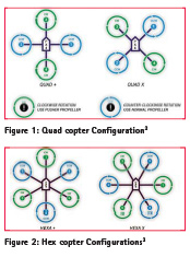
The various design challenges in terms of payload, frame, communication, autonomous flying etc., has to be address before design of a copter. The most usual and popular configuration of a multicopter for practical applications is quad copter and hex copter (Figure 1 & 2). A hex copter has two extra motors than a quad copter, hence, it is more stable and can carry heavier payloads than a quad copter at the expense of extra components. Copters come in various forms e.g. X configuration, + configuration, Y configuration etc. The X configuration provides more thrust and has a higher speed than a + configuration. This is because in case of The + configuration, only one rear motor is present to provide thrust in a particular direction while in case of the X configuration, two motors are present. In case of the + configuration, a FPV (First Person View) or any camera for that matter are generally obstructed by the propellers while in case of the X configuration, the region between the two propellers provide a clear view.
Design requirements
Following design requirements were taken before choosing the shape of the copter:
a. The copter is supposed to deliver a payload capability of 2.5-3.5 kgs for accommodating different kind of application specific sensors (e.g. RGB camera, Multispectral camera, Hyperspectral camera, Thermal camera etc.).
b. It should hold a flight endurance of approximately 20-30 minutes.
c. It should be capable of manual flying, GPS aided flying and autonomous flying.
d. It should possess a radio control range of 2 Kms radius.
e. The plan should be uncomplicated and cost effective.
After studying the above essentials, it was determined that a Hex copter with X shape (Figure 2) is best fitted for the requirements considering the diverse range of applications.
Here, we consider making a Hex copter of certain AUW (All Up Weight) suitable for different remote sensing applications. AUW includes battery and payload along with the weight of the aircraft. Basic equation (eq. 1) to define the total weight of multirotor should be half of the total thrust generated by the motors for hover condition at 50% of throttle.
Total Thrust = 2 x AUW (1)1
In short, to lift 1000 grams Hex copter we need 2000 gram thrust.
Selection of components
A Hex copter/multirotor can be divided into seven main sections, the frame, the propulsion, the power, the radio control, the flight control system, the ground station and on-screen display unit and an additional section which is not required for flight, but for a mission in general, the payload. Each of these sections is dependent on one another to achieve a fully functional and efficient multirotor system. Broadly speaking, the frame provides the structural platform to place all our systems onto. The frame of the multirotor system provides a platform to place the components of the multirotor and also protects them from FOD (Foreign Object Debris). The propulsion system is what lifts the multirotor system off the ground. The propulsion system generally consists of the propellers, the motors and the necessary driving electronics. The flight control system is the nub of the moderator and it controls the multirotor making it fly accurately and in a stable manner. The flight controller generally consists of a microcontroller, sensors and a receiver to gather data from the ground station. The ground station is where information is set from to the multirotor. It can be in the form of a simple remote controller to an elaborate setup of computers and other data acquisition devices. Finally, the payload is what drives a multirotor system to be built or multirotor designs are based around the payload.
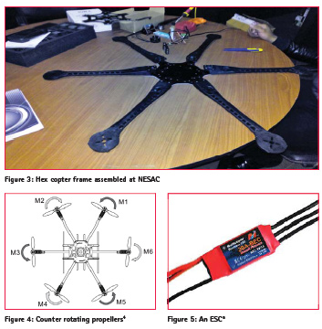
Frame: The one we selected is a symmetric X configuration (Figure 3) frame
It has a metal central plate and side arms are made of carbon fiber material. The weight of the assembled frame is about 3.5 kgs and the diagonal distance is about 80 cms.
Propulsion
The propulsion system of a multirotor is responsible for providing the required thrust for the multirotor system. The components and parts required to move a multirotor system include the propellers, brushless motors and ESCs (Electronic Speed Controller). One must choose the appropriate combination of these factors to generate the needed thrust.
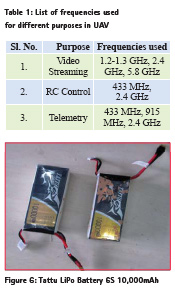
The propellers are divided based on the diameter. A larger diameter propeller will generate more lift than a propeller at the same angular speed as it encompasses a larger area per revolution. Nevertheless, due to the larger size, more torque will be needed to run the propeller at the same angular speed. Likewise, a larger propeller cannot change its angular velocity quickly because it delivers a larger inertia compared to a smaller propeller due to its larger mass (Henderson, 2016). The propellers are always Counter-rotating (Figure 4). The reason for that would be that the counter rotation motion cancels out the torque on the multicopter due to each propeller.
The motors which are employed for this purpose are brushless DC motors. In a traditional brushed motor the outer permanent magnet is fixed while the coils move (Titus, 2012). These brushless motors provide larger torque, better efficiency, longer life and lower noise due to the lack of connecting parts which would have otherwise lead to wear and tear of the material. The brushless motors available in the market are divided primarily based on their Kv rating. The Kv rating of a brushless motor determines the RPM (Rotations per Minute) of the motor per volt applied when there is no load attached. For example, an 1100Kv motor will rotate at 1100 RPM when 1 Volt is applied. A lower Kv rating will provide a motor with larger torque with lower RPM while a higher Kv rating will provide a motor with lower torque but with larger RPM. It is to be noted that most datasheets provide the thrust provided by common propellers at different voltages/ power. The motor used in this project is DJI E800 with Kv rating of 350 Kv along with 13 inches propellers. The combination provides a maximum thrust of 2100 g/motor and a recommended takeoff weight 800 g/rotor. Since Hex copter has 6 such motors a total of 5.4 kgs of total uplift weight is recommended. The weight of fully assembled aircraft is about 3.5 kgs hence the aircraft provides a payload capability of about 1.9 kgs.
An Electronic Speed Controller (ESC) is an electronic circuit (Figure 5) with the purpose to vary an electric motor’s speed, its direction and possibly also to act as a dynamic brake. ESCs are often used on electrically powered radio controlled models, with the variety most often used for brushless motors essentially providing an electronically generated three-phase electric power low voltage source of energy for the motor. Electronic Speed Controllers (ESC) are an essential component of multirotor that offer high power, high frequency, high resolution 3-phase AC power to the motors in an extremely compact miniature package. The one used in this project is a 20 Amps ESC.
Radio control
Radio controls are used to transmit the live video feed and the telemetry data from the aircraft to the Ground Station and control inputs from ground to aircraft. It is important to choose the right frequency for intended use and flying environment. Drones are used in different radio frequencies, so one need to make sure that those frequencies are allowed in the country of usage. The ISM band was born for such a reason. The industrial, scientific, and medical radio band (ISM band) refers to a group of radio bands or parts of the radio spectrum that are internationally reserved for the use of radio frequency (RF) energy intended for scientific, medical and industrial requirements rather than for communications. The commonly used radio frequencies for UAVs are as mentioned below in the Table 1. The frequencies which we have chosen are 433 MHz for command transmitter, 2.4 GHz for ground station and 5.8 GHz for live video transmission of onboard camera.
Power
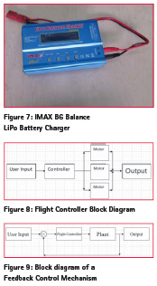
The battery is the source of all power in a multirotor. The most popular battery in the RC (radio Controlled) Flight community is the LiPo (Lithium Polymer) battery. LiPo batteries come in many shapes and sizes and are very light, have a very large specific energy (compared to other electrochemical energy sources) and have a very high discharge rate, and to top it off, it is rechargeable (Linden, et al., 2002). These features make it very popular in the RC Flight community. However, a LiPo battery cannot be charged conventionally. A special LiPo battery charger is required. This LiPo battery charger will evenly charge all cells in the battery. The even charging of the cells in the battery will ensure the battery can be used for a larger number of charge cycles. Figure 6 shows a typical LiPo battery used in RC Aircraft application while Figure 7 shows a commonly used LiPo battery charger which can evenly distribute the voltage across the cells as the batter is being charged. The one which we used in this project is 6 Cell LiPo battery of 10,000 mAh capacity (Figure 6).
Flight control system
The flight control system of a multirotor system is the heart and the brain of the multirotor. A multirotor is a very complex system with multiple variables and outputs. The flight controller (FC) gathers the input from the user and converts it into signals which will then be distributed to the motors which will in turn provide the desired output. A simple block diagram of the flight controller is given in Figure 8. We can observe in Figure 8 that the controller distributes the commands from the User to the motors to provide the desired output. An example of the controller coming into play is when the user wants to turn the multirotor about its yaw axis. To achieve such an output, the controller commands certain motors to turn faster while slowing down the others to create the necessary output.
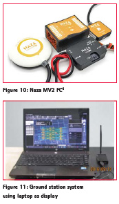
However, the multirotor does not always respond the way it is expected to due to external interferences. This interference or noise will create an unstable and unsteady flight of the multirotor. To counter these interferences and noise, a feedback control mechanism is implemented in almost all multirotors. A feedback control mechanism (Figure 9) uses the error between the input and the output to provide extra input commands to the motors to correct the error. Here we have used NAZA FC V2 (Figure 10) for our Hex Copter (Mulcahy, 2013).
Ground station
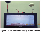
The ground station combines the video receiver(s), display, RC transmitter. Ground stations vary in shapes and sizes from simple screen and receiver mounted atop of the RC transmitter, to a tripod mounted screen with multiple video receivers (diversity box then chooses the best signal to send to the display) and directional antennas. It also gives the ability to do autonomous missions to the rotorcraft. The 2.4 GHz transmitter coupled with its receiver is the most commonly used ground station for a simple multirotor system. Figure 11 shows a ground station system using a laptop as a display device. It gives user the option to do flight planning offline and the upload the mission when the aircraft is connected and do the autonomous flying. User can also give waypoints so that the aircraft follows the same and complete the mission autonomously We have used a laptop as display in our project for ground station tool, along with a 2.4 GHz communication system.
On-screen display unit
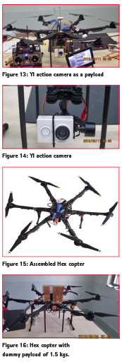
OSD is usually plugged in between the camera and video transmitter. It adds vital flight telemetry data to the image and allows it to be displayed on the operator’s screen. This data can include battery voltage, current, mAh consumed (fuel gauge), altitude, GPS location, home point distance, pitch and roll angles, RC signal strength indicator, and artificial horizon. Some work in conjunction with ground station and can superimpose the aircraft’s location and flight path over digital map. We have used an avionics ODS unit (Figure 12) working on 5.8 GHz link to transmit live video from the onboard camera in this project.
Payload
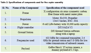
The payload is the driving factor being the construction of a UAV. This payload can come in various forms such as a FPV (First Person View) camera for hobbyists, a high quality video camera for professional aerial photography and videography, multispectral and hyperspectral cameras for remote sensing, goods for the newly proposed AMAZON drone delivery system and LIDAR (Light Detection And Ranging) for surveillance and 3-D mapping. Payloads define the requirements and the requirements define the parameters of a UAV. However, payloads are not necessary for the construction of a UAV. A multirotor UAV can be constructed simply to understand the physics and the working of a multirotor system and the theory behind how it works. Figure 13 and Figure 14 shows a hex copter assembled at NESAC with a YI action camera as a payload. The payload used in this project is a GoPro camera, a YI action camera and a dummy payload of 1.5 kgs weight.
Final assembly
The Table 2 shows the list of major components used in the Hex copter assembled at NESAC. Figure 15 shows the assembled hex copter. Figure 16 shows Hex copter with 1.5 kgs of dummy payload, which has given a satisfactory performance for a flight time of 15 mins at a height of 60 m.
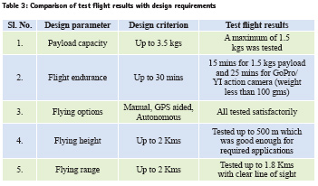
Test flight results
Following Table 3 summarizes the design requirements and achieved performance of the hex copter assembled at NESAC.
Case studies using UAV
The multi rotor based UAV at the Centre has been flown in the areas of North Eastern states of India for specific remote sensing applications, after obtaining necessary permission from the concerned authority. The data has been processed to get valuable products such as orthomosaics, digital elevation/ surface models and 3D point clouds. Soft wares used are Agisoft, Pix4D and ArcGIS. The final products are then shared to the Line Departments for their use in the planning. At NESAC, we are trying to utilize the UAVs for various remote sensing and disaster management applications. Three such case studies are presented in the subsequent sections.
Agriculture
Naramari village of Morigaon District, Assam, India had been reported severe infestation of Boro Paddy by Brown Plant Hopper (BPH) insect (Prasannakumar et al., 2012). As per the request from officials from State Government of Assam, UAV flight was conducted in the affected area and a total area of 0.55 sq. km was covered with a 15 minutes flight. The elevation of the UAV was maintained at approximately 240 m. At this height, ground resolution obtained was about 12cm and the infested areas could clearly be distinguished. Multiple images were obtained with a camera shutter speed of 5 seconds per picture (Figure 17).
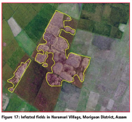
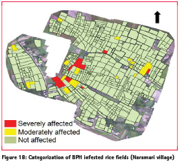
Figure 18 shows categorization of BPH infested rice fields. Rice plots having more than 60% infestation, categorized as severely affected, less than 60% is categorized as moderately affected. It was found that out of total area of 0.58 sq. km, 0.015 sq. km was severely affected and 0.04 sq. km was moderately affected. It has been mentioned that there will be hardly any output from the games categorized as severely affected; whereas with immediate intervention measures, part of the crop area could be saved.
Large scale land use mapping
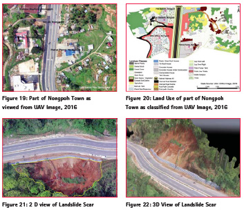
Nonghpoh town is the District Headquarter of the Ri Bhoi district of Meghalaya. National Highway-40 (NH-40) is the life line of Meghalaya State connected from Guwahati, Assam passes across the Nongpoh town. Large scale mapping survey was carried out at the request of the Office of the Deputy Commissioner to support subsequent town planning activities. Flight was taken at 120 m height over the Nongpoh town along the NH-40 for a period of 12 minutes with area coverage of 0.84 Sq. Km. The image was acquired with a ground pixel resolution of 5 cms. The land use information extracted out form the image of part of Nongpoh town (Figure 19) is presented in the Figure 20. Existing land use of the town is comprised of 27+ land use classes including the minor single land features. The quality of the image was further enhanced and necessary GIS tools were used to identify the features. All the land features were correctly identified and mapped in GIS domain. Even, building structure, road types, layovers, open space, even single trees, petrol tanks, etc. could be mapped properly (Figure 20). This type of information will form the basis and accurate information for planning in general and designing technical interventions in particular.
Mapping of landslide affected area
The NH-40 connecting Guwahati to Shillong city is considered to be the life line of Meghalaya State. Some part of the areas along the both sides of the road near Nongpoh is prone to sever landslides. A number of landslides had been occurred already during which caused loss of life and properties. This happens every year during rainy season. Mapping of landslide affected area was taken at the request of District Disaster Management Authority of Nongpoh. UAV was deployed over a landslide area along the road to capture 2D and 3D view of the affected area. UAV flight was carried for about 6 mins and flight height was maintained at 100 m elevation from ground level. Image captured with a ground pixel resolution of 4.64 cms and further processed in GIS domain to estimate the area and volume of the affected sites.
The approximate 3D area (considering the slope) and volume comes out to be 4533.96 sq. m and 7445.26 cubic m (Figure 22) respectively. Terrain 3D length was calculated to be 303.90 m and projected 2D length was calculated to be 277.99 m. These area and volume details can be used for various decision support systems and disaster mitigation tools e.g. an estimate of constructing a retaining wall along the road can be made using the above information so as to minimize the damage for the next time.
Conclusion
This paper has focused more on the rotary wing UAVs (case study: Hex copter) discussing in detail the design and selection of different components based on the requirements and the final assembly. The paper also gives the glimpse of selected remote sensing applications where UAVs can be used. It has been observed that the uses of a rotor based UAV is very specific and limited due to the constraints of the flight time and payload capacity. However, when working within these constraints and limitations, a rotary wing UAV is very efficient in what it does. It has also been observed that the flight controller is a very important component in achieving an efficient and controlled flight of a multirotor. It helps to correct the unstable nature of multirotor-based flight due to the various counteractive aerodynamic and nonaerodynamic forces acting on the aircraft. The overall performance of the system was found satisfactory as per the required applications. However, selection and integration of an appropriate sensor for a specific application is a challenging job. In future, multispectral, hyperspectral and LIDAR sensors can be integrated in the UAV for detailed study of different test sites. However, the weight of sensor remains a critical parameter, as the payload capability of the multirotor UAV is limited. The UAV can also be integrated with onboard image processing capabilities so as to generate 3D maps onboard for indoor mapping applications.
Acknowledgement
We acknowledge the contributions made by Dr. Jenita M Nongkynrih and Shri M. Somerjit Singh Scientist/Engineer ‘SE’, NESAC for supporting the study of images of settlement area and landslide area in Nonghpoh town, Ri Bhoi District, Meghalaya. We acknowledge the support extended by Deputy Commissioner & Chairman District Disaster Management Authority (DDMA), Ri Bhoi District, Nonghpoh, Meghalaya and Directorate of Agriculture, Govt. of Assam and District Agricultural Officer of Morigaon district for arranging necessary permissions and providing field support.
References
1. Colomina, I., Molina, P., Unmanned aerial systems for photogrammetry and remote sensing: ISPRS Journal of Photogrammetry and Remote Sensing A review, ISPRS Journal of Photogrammetry and Remote Sensing, 1 April 2014 pp. 79-81.
2. Dixit, A., Awasthi, A., Akram, V., Sharma, H., Ranawat, D., and Kumar, M., Rajiv Gandhi Proudyogiki Vishwavidyalaya, Bhopal (M.P.), “Fabrication of Drone”, Mahakal Institute of Technology and Management, Ujjain, Bhopal, 2016 pp. 10-13.
3. Elert, G., Author, Illustrator, Webmaster “Chemical Potential Energy-The Physics Hypertextbook”. Physics.info.N.p, 2016. Web [Accessed 13 Sept. 2016].
4. Henderson, T., “Inertia And Mass”. Physicsclassroom.com.N.p., 2016. Web [Accessed 13 Sept. 2016].
5. Higgons, R., Qi3 insight: Unmanned Aerial Vehicles-Growing markets in a changing worlds, February, 2014. [Online]. Available: http://www.qi3. co.uk/wp-content/uploads/2014/02/ Qi3-Insights-White-Paper-UAVs- Growing-Markets-in-a-Changing- World-2014021903.pdf
6. Linden, D., and Reddy, T. B., (eds.) (2002). Handbook of Batteries 3rd Edition. McGraw-Hill, New York. chapter 35. ISBN 0-07-135978-8
7. Mulcahy, C., “DJI NAZA M V2 – Review – RC Groups”, Rcgroups.com, 2013. [Online]. Available: http://www. rcgroups.com/forums/showthread. php?t=1901564 [Accessed 13 Sept 2016].
8. Pannell, D. J., Marshall, G. R., Barr, N., Curtis, A., Vanclay, F. & Wilkinson, R. 2011. Understanding and promoting adoption of conservation practices by rural landholders. Changing Land Management: Adoption of New Practices by Rural Landholders, 2011.
9. Singh, P.S., Saikhom, V., Chutia, D., Gupta, C., Chouhan, A., and Sharma, N., Unmanned Aerial System for Remote Sensing Applications for NER, Reflections, 9(2), 6-7, 2016
10. Prasannakumar, N. R., Chander S., and Pal, M., Assessment of impact of climate change with reference to elevated CO2 on rice brown planthopper, Nilaparvata lugens (Stal.) and crop yield, Curr. Sci., 2012, 103 (10), 1201-1205.
11. Rumerman, J., “Early Helicopter Technology.”Centennial of Flight Commission, 2003. Retrieved 12 December 2010.
12. Titus, J., “Careful Designers Get the Most From Brushless DC Motors”. ElectronicComponentNews.N.p., 2012.Web [Accessed 13 Sept. 2016].
Endnotes
1 “Electronics for You, April 2015”, Google Books, 2016
2 Source: https://code.google.com/ archive/p/arducopter/wikis/PX4RC.wiki
3 Source: http://www.dronetrest.com/t/ connecting-gps-and-motors-on-pixhawk/174
4 Courtesy: http://www.unmannedtech.co.uk
5 Source: www.robotshop.com
6 Source: http://www.rcgroups.com/ forums/showthread.php?t=1901564
The paper was presented at Asian Conference on Remote Sensing (ACRS), Colombo, Sri Lank, 17-21 October, 2016


 (No Ratings Yet)


Leave your response!