| Navigation | |
Calibration method of IMU based only accelerometers
|
|||||||||||||||
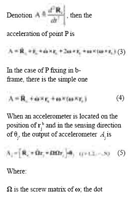
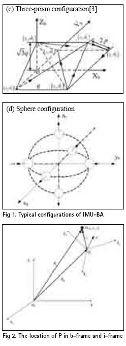
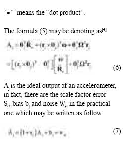
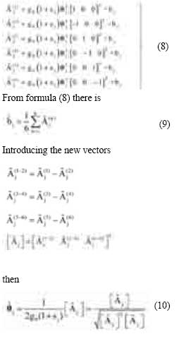
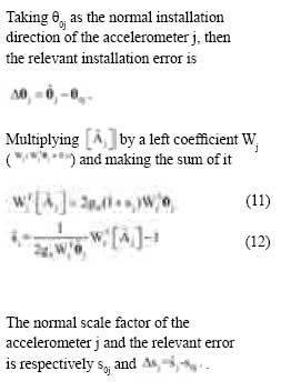
Because of the MEMS inertial sensors being more and cheaper, most studies focus on their applications. It is known that the simple principle and construction of the MEMS accelerometer make it is possible to improve the performance of MEMS accelerometers faster than that of gyros, so most efforts are done to use only the linear accelerometers forming the IMU called IMU-BA which has the potential market in the land and air navigation system, such as the car, air and missile navigation by integrated with the satellite navigation information, and so on, though it can not be used in practice at present. It is obvious that the errors of an IMUBA will be brought by the accelerometer outputs deviating from its correct value. The installation errors and accelerometer errors are the most important two kinds of error sources causing the accelerometer output errors. In order to improve the performance of a IMU-BA, it is necessary to identify and calibrate all of the errors just mentioned above either on-line or off-line as accurately as possible. The accelero-meter errors include scale factor error, bias and noise. The installation errors include both the location and orientation error which means the actual sensor location and sensing direction of an accelerometer have uncertainty associated with the ideal and a significant effect upon the velocity estimates. Some one has reported that the uncertainty in the accelerometer locations is on the order of a few mils. These uncertainties can be calibrated by putting the IMU-BA on the rate table in different appropriate attitudes and other means. Single and multiple accelerometers can be calibrated simultaneously. Part of this work involves building an error compensation scheme employing a parameter estimator for the accelerometer locations and directions. In this paper, one scheme of IMU-BA Navigation Calibration method of IMU based only accelerometers In this paper, the static and dynamic calibration methods are investigated based on the general output equation of an accelerometer. Wu Junwei Professor, Automation College , Harbin Engineering University, China wujunwei@hrbeu.edu.cn in which all of the nine accelerometers directions are parallel to the frame axis, are introduced to investigate the calibration of the installation errors of IMU-BA. In this scheme, six of accelerometers are respectively placed at points located on the three axes and from the frame original, and used to calculate the angular velocity and specific force, the other three located at the original point of the frame and taken as the observation of specific force to bound the angular rate estimate errors. The performance of motion parameters detected depends directly on the sensor and the installation errors in the inertial measurement unit based only accelerometers. In this paper, the static and dynamic calibration methods are investigated based on the general output equation of an accelerometer. Taking the local level or gravity as the reference, the static calibration methods on the sensor error and the installation direction error are given by the multi-position measuring the IMU-BA; driving the IMU-BA in a constant angular speed, the dynamic calibration method is presented also by the multi-position measuring IMU-BA. Typical configuration of IMU-BAIn principle, any IMU-BA formed by six or more accelerometers located in “non-zero” is effective to meet the need of measuring the motion parameters. The typical configurations of IMU-BA are as Fig 1. The output equation of an accelerometerDenoting the point in body-frame as P, the location of P in bodyframe (b-frame) and inertial-frame The output equation of an accelerometerPutting the IMU-BA in six different positions and collecting all of the accelerometer-outputs. The six positions of IMU-BA placed correspond to: axis along with the direction, axis against the direction, axis along with the g direction, Xb axis against the g direction, zb axis along with the g direction, yb axis against the g direction. The outputs of accelerometer j in the six different positions just mentioned are as follow: The dynamic calibration on imu-baThe dynamic calibration is used for calibrating the installation position error of an accelerometer in IMU-BA which needed rotation relative the inertial frame. Driving respectively the IMU-BA in a constant angular speed in there different installation direction in which the rotation axis parallels to the gravity direction, i.e. the rotation axis is respectively in the planes x-z, y-z and x-y. The output of the accelerometer j is[4] ConclusionThe static and dynamic calibration methods may be used for calibrating the sensor and installation errors of an accelerometer in IMU-BA. The local level or gravity may be taken as the reference to calibrate the sensor and installation direction errors in the static condition; the IMU-BA is needed to rotate in a constant angular speed to calibrate the installation position error, i.e. the IMU-BA calibrated must be in a dynamic condition. The direction of the IMU-BA placed is needed select properly both for the static and dynamic methods. References[1] Jeng-Heng Chen, S. C. Lee, Daniel B. Gyroscope Free Strapdown Inertial Measurement Unit by Six Linear Accelerometers. Journal of Guidance, Control and Dynamics. 1994, 17(2): 286-290P. [2] Wu Junwei, Liu Jinfeng. Filter Designed for GPS-Aided Inertial Navigation System Based on Linear Accelerometers. ION GNSS 2006. Texas, USA. 2006.9. [3] Yin Dejin, Wang Hongli. Sixaccelerometer Configuration Scheme for SINS. Journal of Chinese Inertial Technology. Vol.11, No.2. 48-51P. [4] Sou-Chen Lee, Cheng-Yu Liu. An Innovative Estimation Method with Own-ship Estimator for an All Accelerometer-type Inertial Navigation System. International Journal of Systems Science. 1999, 30(12): 1259-1266P. Acknowledgements The authors thank the National High-tech R&D Program of China (863 Program) 2008AA09Z204 for supporting this work. |
|||||||||||||||
|
|||||||||||||||
|




 (No Ratings Yet)