| Navigation | |
Retrospective Gap Filling – the Easy-OBU Way
Easy-OBU is a European Research Project co-funded in the 7th framework of the European Commission and managed by the European GNSS Agency (GSA) |
 |
|
 |
|
 |
|
 |
|
 |
|
Satellite navigation relies on the visibility of a sufficient number of satellites. As the number of satellites increases, some problems such as shadowing in urban areas are reduced although not completely removed. In other instances, such as in tunnels, positioning by satellites is not possible. So the choice here is either to wait until visibility is available again and accept data gaps, or to rely on back-up systems. For land navigation, dead reckoning forms one possibility to measure vehicle speed and turn rate, and combine these information in to a sequence of positions. For accurate data this, however, requires high performance sensors, extra installations with an additional interface to the in-vehicle system, and complex data processing, making it not feasible for most applications. In addition, systems which ensure robust positioning should always contain some dissimilar redundancy. This ensures that a single error event cannot influence all the measurements to the same extent. Consequently, a single error event will be detected by the system and can be isolated, thus enhancing the reliability of the provided positioning information.
If real-time positioning information is crucial then the user will have to rely on expensive and complex solutions. However, many applications do not necessarily need real-time availability, but still would benefit from accurate positional information even with a certain time delay. This applies particularly to many professional applications, such as route controlling, generation of vehicle logs and so forth.
The goal of Easy-OBU is to provide position information with a quality that is comparable to that when navigation satellites are available under conditions when this is normally not possible (e.g., in tunnels). In addition, the system must be affordable, highly flexible and portable. The approach of Easy-OBU to address this is to use, in the absence of GNSS, data collected by inexpensive sensors installed on an OBU. These data are stored and analysed with an intelligent filtering approach (noncausal filtering – NCF) to calculate highly accurate positioning information, while accepting the limitation that this information is only available after a sufficient number of navigation satellites is visible again. Due to the high computational requirements it was decided to perform calculation in a backoffice environment which is linked to the OBU. This also helps to reduce the costs of the OBUs and makes the use of more OBUs, e.g., for car fleets, very efficient.
Basic concept
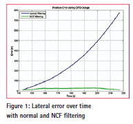
Areas and scenarios where no or insufficient signal reception occur are manifold: tunnels, urban canyons, shadowing, intended or unintended signal distortion interference from various sources, and so forth. What they all have in common is that either no or insufficient information is available to calculate a reliable position. The use of information from inertial sensors in the OBU is one approach to overcome this problem. However, as the outage continues, some errors may rise with quadratic order and can dominate the total error, if the outage period takes longer than a few minutes. The reason comes with the contained deterministic error influences, which cannot be compensated by an inertial navigation computation, if standard filtering is applied. With respect to the vehicle speed, a single accelerometer, without any information about its pitch angle, will measure a small part of gravity as deterministic disturbance that has a dominant impact on the resulting positions. With the continuous integration, even small parts of gravity can lead to significant deviations, with respect to the true velocity computation. Thus, the resulting error of the determined positions can rise very fast. An example for such behaviour is shown in Figure 1, which is based on real measurements carried out in a 1.700 m long tunnel section. With one fibre optic gyro (for the vertical axes) and one accelerometer (for the longitudinal axes of the vehicle) and using normal filtering, the error starts to add up, reaching up to 800 m at the end of the tunnel section even though the applied inertial sensors are of high quality.
If one is a private user these might lead to annoyances, but for professional applications this may have considerable consequences, especially if the system is used for applications which have monetary or legal consequences. Examples of such applications are:
• Insurance (pay per use);
• Route controlling (e.g. for hazardous goods);
• Electronic toll collection (ETC), road user charging (RUC);
• Control of usage behavior for car rental;
• Documentation for winter service;
• Cost determination for Car-Pool;
• Car sharing (pay per use);
• Generation of vehicle logs for public transportation and recording (security service).
What all the aforementioned examples have in common is that they do not rely on real time information. In the end, it is quite enough if correct and reliable information is available by the time invoices are sent out or an account of the work performed is made (e.g., for road maintenance carried out). This leads to the concept to Easy-OBU. The aim is to achieve robust positioning with adequate performance on the basis of low cost inertial sensors and with the innovation of the NCF approach.
The example shown in Figure 1 already demonstrates the large potential of this innovative filtering approach. For demanding applications, this approach can bring an improvement with respect to the weak points of a solely GNSS-based system and provide robust positioning at adequate quality. In contrast to these first tests, the OBU developed for Easy- OBU will feature 3-axis gyroscope and 3-axis-accelerator, providing six degrees of freedom compared to two as used in the tests described above. This can bring further improvements to the stability of the positioning information, but at the same time will increase storage, computational and communication demands. As the concept is not suitable for real-time applications, some of these tasks must not be carried out in the OBU, but can be performed in an external environment. This makes it suitable for different applications and can also increase efficiency for large scale applications (e.g., for whole fleets). In the following sections, the technical set-up of the Easy-OBU system will be discussed followed by the system requirements.
Technical setup of Easy-OBU
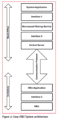
The Easy-OBU system consists of two main elements. One is the on-board equipment in the vehicle, and the other is a central server in a back-office. The OBU and central server are connected via a communication link (see als o Figure 2).
Crucial for the whole system architecture are the interfaces connecting the various elements. The interfaces 1 and 2 are open interfaces and described in a publically available deliverable of Easy-OBU [1]. This ensures that the system does not depend on a specific OBU and that it is up to the user which applications should be run. Internal interfaces of the Easy- OBU system are communication interface between the OBU and the central server and the internal interfaces at the back office (Interface 3). The protocol used for the communication between the OBU and the central server is a proprietary protocol designed for the Easy-OBU system. The other proprietary part of the system is the non-causal-filtering service carried out in the back office. The main tasks of the central server are to:
1. Communicate with all OBUs;
2. Collect data received from OBUs;
3. Adjust position data with noncausal filtering service and
4. Make adjusted position data available to the system application.
The data transfer between the central server, NFC service and system application is realized as a chain of databases.Interface 3 describes the relevant OBU data, which the NFC service needs for position data correction. Interface 1 describes the OBU data which is made available to the system application. Depending on the system setup, the back office can also be a distributed system as the infrastructure of the back-office has no influence on the data flow from the OBUs to the Easy-OBU application database.
In case of a GNSS outage, the Easy-OBU system waits for GNSS re-acquisition and bridges the gap by recalculating the measurements from the inertial sensors, located inside the OBU. Thus, the complete behavior of the vehicle during the outage is known right afterwards (e.g., distance travelled, trajectory, speed direction, etc). Initially the information will be stored in the back office where it can be used for further processing. If required, the information could also be transferred back to the vehicle, although this will not be implemented during the Easy-OBU project.
In order to define the system and performance requirements, different applications were described as listed in section II. With these as a basis, interviews and workshops with potential users and developers were carried out in order to further elaborate and better define the technical requirements. Based on these, the performance parameters for Easy-OBU were defined as follows:
• Availability: > 99.9 %
• Position accuracy: < 10 m (CEP95)
• Heading accuracy: <5° (1 sigma)
• Velocity accuracy: < 2 km/h (1sigma)
• Distance accuracy: < 1 %
• Time accuracy: < 0.5s (1 sigma)
• Update rate 1 Hz In addition, further requirements have to be fulfilled in order to make the OBU attractive for the targeted user community:
• Light weight (< 0.5 kg);
• Small size (view through windscreen should not be disturbed)
• Highly portable and easy to install in vehicles (only connected to power supply of the vehicle);
• Flexible to access through well-defined interfaces;
• Highly affordable, as OBU comes at competitive cost (including vehicle integration); and
• Flexible in regard to its usage, as it may serve a whole spectrum of different applications.
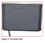
The OBU itself used for the project is small in size (11 cm x 7 cm x 3.5 cm) and can simply be mounted behind any vehicle’s windscreen or on the dashboard (see Figure 3). It needs only to be connected to the car power and car ignition via an adequate fuse.
The OBU has the following main elements:
• GPS module for the processing of EGNOS data;
• Integration of accelerometer sensors in 3-axis, to capture the vehicle speed during GNSS outages;
• Integration of a gyrometer sensors in 3-axis, to capture the vehicle turn rate during GNSS outages;
• Implementation of self-calibration to determine the right levelling (orientation) of the OBU after installation, because each user may cause a different way of installing;
• Extension of the OBU-software for proper measurement acquisition of the additional sensor information;
• Usage of GPS timing capability for exact synchronisation between all measurements and information in the OBU;
• Optimization of the data aggregation inside the OBU and the data fusion of the communicated measurements into the control centre; and
• Analysis of the data content which needs to be transmitted to the control centre, in order to drive the NCF-filtering. As the Easy-OBU has to be able to perform with a wide variety of applications and in very different system environments, it is only possible to examine the system performance for selected examples.
As a start, the sensor and NCF performance was examined, while the performance of the Easy-OBU system will be examined at a later stage, moving more and more to a complete operational environment.
First test trials and NCF
First tests for the technical feasibility have been executed in the region of the City of Vienna and combines urban sections and highways. The goal of these initial tests was to examine how the data recorded from the six inertial sensors (acceleration in three axis and orientation in three axis) can be used with NCF to correctly calculate the acceleration and turn rate.
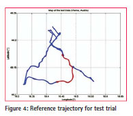
The selected route contains various tunnel sections, which are suitable for the Easy-OBU objectives to provide improved positioningservice into areas, where GNSS signals cannot be received. A map of the covered road sections is presented in Figure 4 on the basis of a reference trajectory. For the initial evaluation of the performance of NCF, a subset was selected (shown in red).
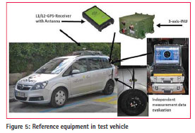
The length of this section is nearly 20 km and the test time is more than 800 seconds, with the test vehicle travelling at approximately 80 km/h on average. The reference data was collected independently in the same vehicle using high quality satellite and inertial navigation equipment (see also Figure 5 ).
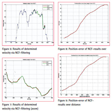
The selected test track contains one tunnel of nearly 2 km length where no GNSS reception is possible. This gap must be bridged with information derived from inertial sensors. In order to examine the result of the NCF methodology, Figure 6 shows the velocity calculated based on GPS data (blue dots) and the bridged gap (during GPS outage) by NCF (red). For comparison, the true reference data (green) is also depicted. It can be seen that between the 580 and 660 seconds no GPS reception was available and that before and after the tunnel GPS returned large errors.
Zooming into the time window in question (see Figure 7), it can be seen that NCF could very well reproduce the velocity during the tunnel section. In addition, NCF is very stable before entering the tunnel and after leaving it.
Figure 8 shows the two dimensional position errors over time for the situation of GNSS outage. Here an error drift can be recognized, which is typical for inertial systems. The parameter of time on the x-axis of the diagram is also the first choice, because the drift rises due to the double integration of the acceleration signals over time. This is in contrast to dead reckoning procedures, which show rather a drift that depends on the distance travelled. In Figure 9 the position error is shown with the distance travelled on the x-axis of the diagram. From the shape of the error behavior both plots look quite similar. This is again due to the road character of highways and the fact that the vehicle was driving with a speed of around 80 km/h with little acceleration or deceleration activities.
Conclusion and outlook
In this paper, the basic concept of a system for retrospective gap filling was presented. This system is based on an on-board unit fitted out with low costs sensors. In the event of loss of satellites data from these sensors are stored in the on-board unit and, once satellite visibility is available again, transferred to a back office were these data are used to calculate the route using non-causal filtering operations. The advantages of this system are that it provides high accuracy positioning data which would otherwise not be available at very low costs with the addition of high flexibility and transferability. A number of cases have been identified which could benefit from such a system. First tests have already shown the stability of the non-causal-filtering operations with data derived from low cost sensors in the absence on GNSS signals. In the next step, the system will be further developed and tested with potential users in order to test the usability of it and provide feedback for further improvement. The community at large will benefit from the open system approach, as it can be used irrespective of the type of OBU and the type of application foreseen.
Acknowledgment
The research leading to these results has received funding from the European Union Framework Programme (FP7/2007-2013) under grant agreement no.: 287217.
References
[1] Easy-OBU Deliverable; D2.2: “Open System Interface Specification”; Version 1.0; December 2012.


 (3 votes, average: 2.67 out of 5)


Leave your response!