| Mapping | |
VISAT: Mapping what you see
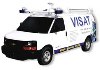
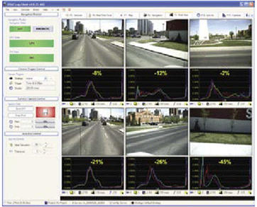
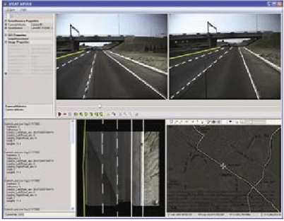
VISATT – System componentsAlthough all mobile mapping vans share the same concept of direct georeferencing, they carry different types and grades of sensors depending on the application, integration scheme, and the required accuracy. For example, vans which are used for highway maintenance are equipped with a single GPS receiver and a single camera to detect the locations of asphalt defects with accuracy of few meters. In general, a mobile mapping van integrates navigation sensors and imaging sensors that can be used to determine the position of imaged points. All the sensors are rigidly mounted together on a platform; the former sensors determine the position and orientation of the platform, and the latter sensors determine the position of points external to the platform. The sensors that are used for the external position determination are predominantly photographic sensors and thus are typically referred to as imaging sensors (El-Sheimy, 1999). sensors (El-Sheimy, 1999). However, additional sensors such as laser rangefinders (Li et al., 1999) or laser scanners are also used in MMS and therefore the more general terms of mapping sensors or relative sensors may also be used when referring to the remote sensors (Ellum and El-Sheimy, 2001). Generally speaking, the final system quality depends on the accuracy of the used sensors and their hardware/ software integration schemes. The core hardware components of the VISATT van are a Strap down Inertial Navigation System (SINS), a dualfrequency GPS receiver, and a cluster of digital color cameras. The primary purposes of these components are – the GPS provides the position of the van, the SINS provides the orientation of the van, and the cameras are used for relative positioning from the van. These components, however, also have important secondary functions. For the GPS, these secondary tasks include controlling the long-term error growth of the SINS through the GPS/SINS Kalman filter and providing the precise timing base for all data streams. The secondary tasks of the SINS stem from its ability to be used as a position sensor in addition to an orientation sensor; consequently, these tasks include bridging GPS signal outages, detecting and correcting GPS cycle slips, and precise interpolation between GPS positions. The latter task – interpolation between GPS positions – is possible because the SINS provide data at 200 Hz, while the GPS positions and velocities are only available at 1-2 Hz. Figure 1:VISATTM Van Mobile Mapping System In addition to the GPS, SINS, and cameras, the VISAT system also integrates a Distance Measuring Instrument (DMI). The pick-up from the DMI is used to trigger the acquisition of the images from the cameras at constant distance Table 1: Primary and Secondary Functions of VISAT Sensors Figure 2: VISATT Log Application Running in VISAT Van intervals defined by the user. Table 1 summarizes the primary and secondary tasks of the sensor in VISAT. Currently, the VISATT imaging component consists of 6 to 12 progressive color digital cameras (1600 x 1200 pixels or 2048 x 2048 pixels) which provide a 280 to 3600 field of view. The images are captured at high sampling rates and can be controlled by either time or traveled distance (usually every 2-7 m). The images are captured while the van is moving at the highway posted speed (up to 125 km/h). Essentially, all navigation and mapping data streams are synchronized to a common time frame using a high frequency synchronized multi-channel clock. VISATT has an efficient and robust data logging module which enables the collection of the data with minimum time delay. The VISATT logging system (see Figure 2) also has an expert module for real-time quality control, which communicates with the system’s operator and provides useful information such as length of the survey, distance to master station, directions to specific routes, etc. VISATT – Operational cycleVISATT provide a task-oriented implementation of mapping concepts. Surveying by VISATT consists of three steps, which are essentially the same as for any mobile mapping system: VISATTM Geolmages Server Architecture more georeferenced images. All data collected by the VISAT van is post-processed. During the post-processing, the digital images acquired from the VISAT van are georeferenced using the position and orientation as determined by the GPS and SINS data. The system position and orientation are interpolated at the instants of image exposures and then combined with the system calibration parameters, as described by lever arm and boresight angles, to relate the images to the real world coordinate system (El-Sheimy, 2005). The georeferenced images are hosted on VISATT GeoImage Servers along with the camera calibration that describes the inner orientation of the sensors, and the system calibrations that describe the lever arm and boresight angles. This new generation of servers allows client access via .NET Remoting on TCP, HTTP, or Named Pipe channels for desktop, workgroup, or internet deployment and distribution. VISATT GeoImage Servers also act as a Universal Description Discovery and Integration Service (UDDI Web Service). The distributed three layers architecture of the server, Login and Security, GeoImage Metadata, and Image File Server architecture can accommodate for mega size VISAT Image Libraries by using VISATT Station Measurement Network Load Balancing (NLB) and Server Clustering techniques. The next stage is the extraction of 3-D coordinates from the images. In addition, geometric information and attributes of themed objects such as control points, utility lines, and land parcels may be needed to form GIS elements for themed layers. This task is performed using a photogrammetric workstation called the VISAT StationT that enables the measurement of objects appearing in the images and the generation of GIS elements. VISATT Station is the client application that enables the user to make use of the collected georeferenced images and perform mapping and GIS editing. The georeferenced images are accessed from a local file on the user’s desktop or by logging on to one of the VISATT GeoImage Servers on the enterprise’s Intranet or by subscription to public servers on the Internet. Point features are digitized by measuring the point in at least two images. The 3D point coordinates are obtained using simple photogrammetric intersection. Attribute information can be also collected by assigning the appropriate point symbol for the point feature. VISATT data are easily populated into GIS software like ARC-GIS. Automated Road Vector Extraction Engine (ARVEE) is a VISAT software component, especially designed to automatically detect and extract road lane line markings and road edges. ARVEE is an automated component running as a service on VISATT GeoImages Server that automatically process or re-process new or update georeference image files placed on the server. ARVEE derived information contains the 3D lane line vectors, their color and line type attributes. The 3D Road Vectors are also used in the Automated Quality Control Service (AQCS) of the server infrastructure and can easily be integrated into GIS platforms providing a vital method for creating and/or updating an important GIS layer for the next generation of Advanced Car Navigation, Driver Assistance Systems, and Fleet Management Services. (Wang et al., 2007 and El-Sheimy et al., 2007). VISAT™ Arvee Application Mobile mapping -future outlookMobile mapping for land vehicles, the combination of digital imaging and georeferencing, has developed from a topic of academic interest to a commercially viable industry with several applications. The VISAT technology, presented in this paper as an example of MMS, offers a system which is unique in several aspects: . it offers a high-accuracy (10 – 30 cm RMSE) georeferenced imagery-based data product With the rapid development of highresolution digital frame cameras and the current development of laser and other sensors, economy and efficiency will continue to improve for MMS. The future of MMS is nothing short of promising and exciting. For example, the next generation of VISATT, the VISATT Van 3D Modeler which is currently under development with a prototype expected in early 2008 will include a terrestrial laser scanner for 3D modeling applications, enabling the user to “view” a photorealistic 3D model of the streets, surrounding buildings, road surface, etc. Future extension of the VISATT Van 3D Modeler includes the integration of multi-spectral sensors, infrared, and ground penetrating radar (GPR) with the overall objectives of providing a system capable of producing 3D virtual cities. This is just the beginning – MMS, VISAT included, truly provide a faithful capture of mapping what we see. |


 (3 votes, average: 1.00 out of 5)


