| GNSS | |
The ‘Namuru’ Open GNSS Research Receiver: An update
|
||||
|
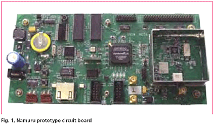
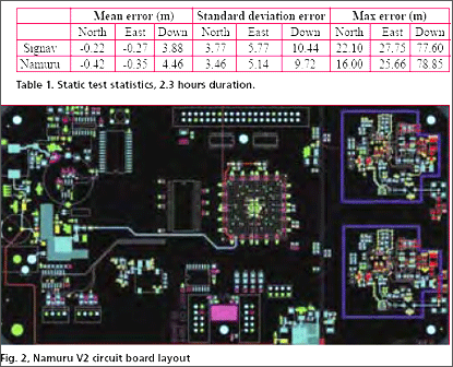
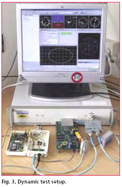
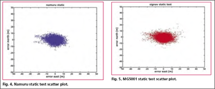
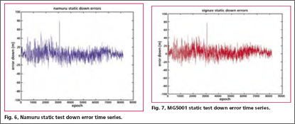
Development of a Field Programmable Gate Array (FPGA) based GNSS receiver platform has been underway at the University of New South Wales (UNSW) ‘SNAP’ lab since 2004. The receiver now has a name; ‘Namuru’ that means ‘to see the way’ in the language of the Eora people who inhabited an area around Sydney, including the UNSW campus, before the arrival of the British. The receiver was introduced in the Coordinates January 2006 edition and in this article we first provide a brief recap and then look at the latest developments and results from testing. But before launching into this, the question of why such a research and development platform is desirable must be answered. GNSS research development platformsDevelopment platforms (or kits) come in two main flavors; 1) Application Specific Integrated Circuit (ASIC) based GNSS receivers with application firmware that can be modified to some extent and 2) Software based receivers that run on a PC, often with external Radio Frequency (RF) front end hardware. Type 1 kits include Mitel’s GPS Architect, the Signav MG5021 and the uBlox Antaris SCKit. These kits include application firmware that can be modified, and target hardware based on ASIC chips that are typically small, low power, inexpensive OEM boards. Note that the GPS Architect is no longer supported or available but is important as it has become some sort of standard reference design. Type 2 kits include offerings from NordNav and Accord that provide USB RF frontend hardware and software receivers that run in real-time on a PC, and Data Fusion Corporation that offers a Matlab solution that does not run in real-time. These can provide great flexibility in receiver design, but do not map very well to current portable devices due to high processing demands. This is due to the fact that while an ASIC GNSS baseband processor provides parallel signal processing, a general purpose processor such as an Intel Pentium 4 must do this work in series. Of course, as processing capacity increases and power consumption decreases this becomes less of an issue and eventually the flexibility of the software approach will be available on portable devices. The Namuru receiver falls between these two types (I’ll call it type 3) and therefore can fill a gap, providing more design flexibility then type 1 platforms, but not requiring the high power processor of type 2 platforms. Designs realized on type 3 platforms potentially have a better defined migration path from development to commercial product than developments on type 2 platforms. In addition, the Namuru platform is an open source project, where all aspects of the design are freely available. Research potentials for NamuruMany possibilities have been identified for the Namuru platform, and the list can extend as far as your imagination permits. Broad areas of activity include: • developing GNSS IP for integration with other functions in an FPGA-based device Receiver design research streams include: • Weak signal and multi-path mitigation techniques Namuru OverviewThe platform has three components; circuit board, baseband processor design and application firmware. The prototype circuit board has been built and verified, and a new board is currently being designed. The prototype board includes: • L1 RF front end based around the Zarlink GP2015 chip The new board (Namuru V2) will be a short production run and will include: • Two front ends – 2 x L1 or L1 + L2 The baseband processor is realized on the FPGA chip and is written in Verilog and VHDL. It nominally has 12 channels, and is traditional in design. It attaches to an Altera NiosII soft-core processor (also on the FPGA chip) as a memory-mapped peripheral. More details on the design can be found in the Jan 06 Coordinates article and on the Namuru website. The application firmware controls the baseband processor, collecting measurements, forming pseudoranges, calculating the position/velocity/time (PVT) solution and communicating with the user. The firmware runs on a NiosII processor and is developed using Altera’s NiosII integrated development environment. Currently the application firmware is a port of the Mitel GPS Architect. The GPS Architect was available for some TestingFor testing purposes, the Namuru and a reference receiver where connected to the same RF source via a splitter and data was collected and analyzed under static and dynamic scenarios. The reference receiver was a Signav MG5001 running the GPS Architect firmware, providing a very similar platform for confirming the correct operation and performance of the Namuru receiver. For static testing, the RF source was real GPS signals from an antenna mounted on the roof of the Electrical Engineering Building at UNSW. For dynamic testing, the signal source was a Spirent GSS6560 Multi-Channel GPS simulator, running a number of scenarios, including simulating an airplane flying round in circles at a fixed height and speed. Results from one static test and the airplane scenario are presented here. Static testThe static test provides a basic feel for the overall performance of the receiver once it has acquired satellite signals and providing a PVT solution. The statistics of the error from the ground truth provide an indication of the position performance of a receiver. Scatter and height time-series plots, along with a table of statistics are provided for both the Namuru (in blue) and Signav MG5001 (in red) receivers for a static test of around 2 hours duration. The message hevre is that there is no significant difference between the two receivers performance for this test. |
||||
Pages: 1 2



 (No Ratings Yet)


