
| GNSS | |
gSim – Low Cost Dual Frequency GPS & Galileo Simulator
We proved the concept of the generation of perfectly coherent dual frequency navigation signals using an SDR transceiver |
 |
|
 |
|
 |
|
 |
|
Summary
• GPS L1/L5 and Galileo E1/ E5a software simulator that uses cheap off-the-shelf SDR transceivers augmented by a gSim Converter for signal generation
• Customizable static and movement user scenarios, including LEO orbit • Generation of line of sight and up to two reflected or spoofed signals with the same or different navigation message
• Modelling the errors in the navigation message channel
• Rich set of navigation scenarios for demonstration of the simulator function, performance, and capability
Introduction
The massive use of GNSS navigation products both for stand-alone and embedded systems and applications raises the need for custom testing of these devices. This paper describes a novel approach to the development of the multi-frequency and multi-system GNSS simulator. The development itself was initiated by our colleagues from the automotive and railway industries, who questioned the high prices of the commercial GNSS simulators and also our need for complex testing of the CubeSat GPS receivers [1]. The first idea was to use common off-the-shelf SDR (Software Defined Radio) [2] transceivers for signal transmission. The same approach also uses an open-source GPS simulator [3].
Let us recall that GNSS systems operate on the timing principle. The receiver calculates the position from the so-called pseudoranges, which are calculated from the time of arrival of satellite signals to the receiver. Since satellite signals are perfectly synchronized by onboard atomic clocks [4, 5] the simulated signals must have the same properties. The critical problem is then to achieve perfect coherence of the code and carrier frequency and coherence between signals at different navigation frequencies.
The low-cost SDR transceivers can generate a signal with a bandwidth of several tens of megahertz; in the case of multiple frequency generation, several transceivers have a dual channel architecture, but the generation of perfectly coherent signals on both channels is not possible in their simple cost-reduced approach. The ideal solution (Figure 1.) is to generate coherent complex envelope signal samples for all supporting frequencies. The samples are then digitally upconverted onto the carrier frequency by DUCs (Digital Up Converter), summed up and converted to the digital domain by DAC (Digital to Analogue Converter), and reconstruction Low Pass Filter (LPF) [6]. Unfortunately, the hardware capable of the described approach is expensive and is one of the main factors that determines the price of the simulator.
The approach used in the gSim simulator is different, as described in Figure 2. We generate one intermediate frequency data stream that comprises the signal of all satellites on both supporting frequencies. Such signal is firstly modulated onto the intermediate frequency using a standard commercial SDR transceiver. The resulting signal is then shifted onto the navigation carriers by a following frequency converter (gSim Converter) using band pass filters to suppress undesired spectral components produced by the mixer. More details are in the Hardware section or [6].
Software
The aim of the software is to generate signal samples for SDR transmitter based on the scenario and other supporting data. The main design requirements are:
1. Dual frequency GPS L1C/A & L5 and Galileo E1b&c and E5aI&Q signals with future update to add GPS L1C and BeiDou B1C & B2a
2. Capability of static and dynamic user motion scenarios
3. Estimation of the navigation satellite clock, ephemeris, and other supporting data for any time derived from navigation messages measured by a monitoring receiver
4. One update of the navigation message per simulation
5. Generation of a line of sight and up to two reflected signals
6. Modulation of one reflected (spoofed) signal by a different navigation message
7. Modification of the content of the navigation message and modelling of the errors in the navigation data channel
8. Simple software control for common scenarios
9. Possibility to use a third-party data processing or mathematical software for the realization of complex simulation scenarios
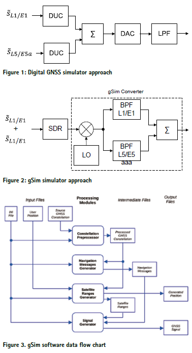
The gSim is designed as a Linux command-line application that consists of four processing modules. The data transfer and mutual link between modules are clarified by the data flow chart in Figure 3.
There are three basic groups of files in the processing chart: input, intermediated, and output files. The input and intermediated files are human-readable files that can be manually modified by any text editor or by automated text processing with third-party software [6]. This enables the design of complex simulation scenarios, construction of complex multipath and signal propagation environments, spoofing attacks, modelling the errors of the control segments, signal propagation, etc.
Simulation scenario setup
The simulation scenario is defined by a human-readable INI File that uses standard syntax based on key-value pairs. gSim INI file is organized into eight sections. The user can set the basic simulation parameters like simulation start time and duration, switch on and off particular GNSS signals, individually set their level and number of reflected signals, sampling frequency, intermediate frequency, frequency offsets of individual systems and signals, configuration of SDR transceiver, navigation messages, folder structure, and many others.
The user position or its movement is defined using the User Position file. The last part of input f iles is Source GNSS Constellation Files, which store GPS and Galileo orbital parameters.
Constellation Preprocessor
The first data processing is the transformation of the source GNSS constellation data to the time of the simulation. The gSim enables one update of the navigation messages in signal content during simulation. Therefore, it is necessary to generate up to two navigation messages constellations, one that is modulated before the update and the second one after the update. The last satellite position constellation files are used to calculate the positions of the navigation satellites.
This complex data processing is done by a Preprocessor module in two possible modes. The automatic mode operates with a simplified setting where the user must set only the start time of the simulation. The preprocessor then automatically generates regular navigation updates and reference times.
In manual mode, all the processes are under complete user control. It is possible to set extraordinary navigation messages update independently for each satellite, set irregular user reference times, etc.
Navigation Messages Generator
The Navigation Messages Generator creates navigation messages for all satellites based on the navigation message constellations. The results are human-readable Navigation Messages files that contain commented navigation messages that can still be modified before signal generation. The user can change almost all the values of individual items, set the errors in the communication channel. The full set of possible adjustments can be found in [2,3].
Satellite Ranges Generator
The purpose of the Satellite Ranges Generator is to calculate the ranges files of individual navigation satellites that contain signal delay on both supported frequencies. The setup of the gSim enables to introduce to the signal ranges both ionospheric and tropospheric delay.
With the help of suitable third-party software like GNU Octave, SciLab, Matlab, Python, the user can add up to two reflected signals, model the signal propagation, introduce the spoofed signals, and many other phenomena.
Signal Generator
The final processing block is a Signal Generator that finally builds the resulting baseband signal samples of the GNSS signal. The signal generator is designed as a multithread application and is capable of using all the processing power of a multicore processor for signal generation (with the proper choice of initial parameters in input files).
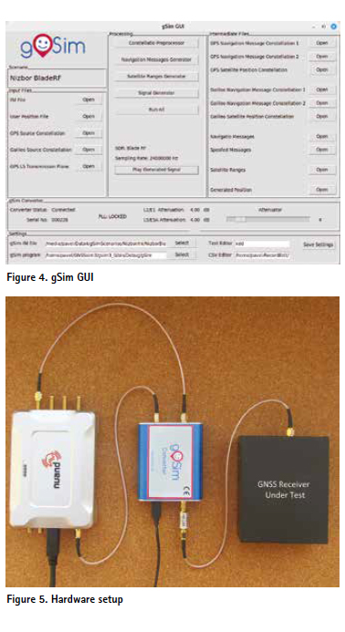
GUI
To simplify gSim control, the simulator uses a GUI (Figure 4) that was developed to enable more user-friendly access to simulation setup in comparison with plain text files editing. The GUI allows you to open and edit input and intermediate files, run individual processing models, and transmit the generated signal using an SDR transceiver. Last, the GUI displays the gSim Converter status and controls the electronic attenuators built into the gSim Convertor, thereby controlling the generated signal level.
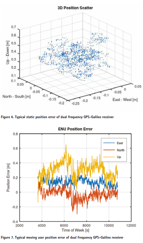
Hardware
The hardware interconnection is quite simple, as can be seen from one possible configuration shown in Figure 5. The hardware setup consists of a PC computer (not shown) for signal generation and playback. The SDR transceiver modulates the signal at an intermediate frequency. The simulator can set the sampling frequency, intermediated frequency, and the frequency offset of individual GNSS signals in a wide range. That enables to fit the simulator to various SDR transmitters.
The intermediate frequency signal is then moved to the final navigation carriers L1/E1 and L5/E5a with the help of gSim Converter (Figure 2). The signal level is adjusted by built in digital attenuators and an external 30 dB attenuator. The last block in the picture is the GNSS receiver under test.
Simulation Scenarios and Test Results
In the frame of the gSim project, several simulation scenarios were prepared for general gSim testing and demonstration of its performance. The simulation scenarios cover static, dynamic and time/leap second changes and are fully described in [8].
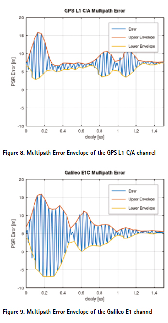
Absolute position precision
The simulator enables testing of the GNSS receiver absolute position errors of the static and moving user computation. The examples of the test results for static and moving users are in Figures 6 and 7. The dynamic position error analysis is done with the help of a Generated Position file that contains precise time and coordinates of the generated signal, see Figure 7.
Besides classical simulation scenarios for position error investigation, gSim enables testing of receiver’s response to errors in the communication channels, modification of the content of the navigation message, and many others.
Multipath Error Envelope
The reflected signal generator enables the simulation of complex multipath environments or testing the sensitivity of the navigation receiver to the reflected (multipath) signals. The classical method is based on the investigation of the pseudorange errors caused by one reflected signal for various phase shifts between the Line of Sight and the reflected signal [9]. The maximal positive and negative errors are then expressed as a multipath error envelope.
The methodology of testing the dual frequency receiver using gSim is straightforward. We affect the signal on one frequency with the multipath signal, while the signal on the second frequency is without the multipath signals. This approach enables an easy evaluation of the multipath impact by comparing the multipath-affected reception to the default “clean” reception. The example of the multipath error enveloped measured on GPS L1 C/A and Galileo E1 signals are in Figures 8. and 9.
The simulation was realized using a simple GNU Octave script [8] that adds reflected signals with attenuated amplitude with growing delay and small Doppler shift to the Satellite Range File of selected GPS and Galileo satellites. The raw pseudoranges measured by a GNSS receiver under test were analyzed using the Octave script.
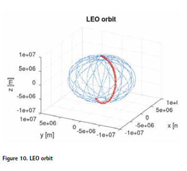
LEO Orbit
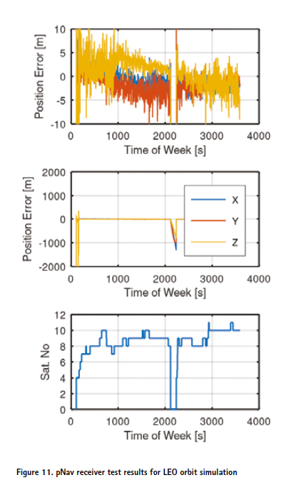
gSim can also be used to test space based GNSS receiver applications like e.g. LEO orbit satellites position determination, Figure 10. An example of the application is a test of the pNav L1 GNSS receiver designed for small satellites equipped with an orbital propagator, allowing a deduced reckoning navigation. The algorithm is based on the numerical solution of the satellite equation of motion. The results of the gSim generated signal transmitted to pNav receiver can be seen in Figure 11.
At approximately 2100 s, the signal was intentionally attenuated by the attenuator in the gSim Converter. The receiver lost satellites and went into interpolation mode. After the signal was restored, the receiver continued with standard navigation using simulated GPS satellites.
Other test scenarios
Leap Second
gSim can test the receiver response to the leap second event [10]. The creation of the simulation scenario is simple; the user generates simulation scenarios for the midnight when the leap second is inserted or removed. The next step is to manually set the UTC parameters in navigation message constellations modulated before and after midnight. Details for parameter adjustment are thoroughly described in [3].
Dynamic stress
The next interesting task that the gSim can be used for is testing dynamic stress errors or receivers [11]. Let us note that the GNSS receiver channels use DLL, PLL, and FLL (Delay, Phase, and Frequency Locked Loops) for signal tracking. Such feedback loops are sensitive to the dynamic stress of the tracked parameters [11]. gSim enables the creation of scenarios to investigate those errors.
Intelligent spoofing
GNSS jamming and spoofing [12] are emerging problems nowadays with a broad range of positioning services. gSim enables the simulation of satellite signals and one spoofed signal that can be modulated by a different navigation message. This allows complex receiver testing for spoofed signals and modelling sophisticated spoofing attacks.
Conclusions
The developed dual-frequency GPS Galileo simulator based on the low cost SDR can be used for testing and verification of GNSS receivers operation under various controlled conditions. We proved the concept of the generation of perfectly coherent dual-frequency navigation signals using an SDR transceiver. The simulator is available on the gSim website for public use in its simplified mode, along with the documentation and demonstration simulation scenarios. The large simulator flexibility was reached by the decomposition of the data and signal processing into four phases with simple well-described interfaces that enable the use of third party mathematical or data processing software like GNU Octave, or Python for the realization of complex scenarios. The modular concept enables to use all or just selected parts of the gSim for simulation signal preparation or adjustment of generated GNSS signals.
Acknowledgments
The project was realized as a private initiative of the authors as part of their extra-university activities to practically verify a low-cost generation method of the dual-frequency GNSS signals. The Czech Technical University in Prague supports the project’s commercialization: https://fel.cvut.cz/ en/cooperation/for-companies/offer of-technology/gnss-simulator-gsim.
References
[1] P. Kovar, Experiences with the GPS in Unstabilized CubeSat, International Journal of Aerospace Engineering. 2020, 2020 ISSN 1687-5966.
[2] D. M. Molla, H. Badis, L. George and M. Berbineau, “Software Defined Radio Platforms for Wireless Technologies,” in IEEE Access, vol. 10, pp. 26203-26229, 2022, doi: 10.1109/ACCESS.2022.3154364
[3] Takuji Ebinuma, Gps-sdr sim, https://github.com/osqzss/ gps-sdr-sim, access Jan 1. 2025
[4] C. Dionisio et al., “gLab a fully software tool to generate, process and analyze GNSS signals,” 2010 5th ESA Workshop on Satellite Navigation Technologies and European Workshop on GNSS Signals and Signal Processing (NAVITEC), Noordwijk, Netherlands, 2010, pp. 1-7, doi: 10.1109/NAVITEC.2010.5707988.
[5] C. J. Hegarty, “GNSS signals — An overview,” 2012 IEEE International Frequency Control Symposium Proceedings, Baltimore, MD, USA, 2012, pp. 1-7, doi: 10.1109/FCS.2012.6243707.
[6] AMD RF Sampling, https://www.amd. com/en/products/adaptive-socs-and-fpgas/ technologies/rf-sampling.html#resources
[7] Pavel Kovar, gSim User Guide, www.gSim.cz/Downloads/
[8] Pavel Kovar, gSim Simulation Guide, www.gSim.cz/Downloads/ [
9] Irsigler, Markus, Hein, Günter W., Eissfeller, Bernd, “Multipath Performance Analysis for Future GNSS Signals,” Proceedings of the 2004 National Technical Meeting of The Institute of Navigation, San Diego, CA, January 2004, pp. 225-238.
[10] M. Hack, X. Meng, S. Froehlich and L. Zhang, “Leap Second support in computers,” 2010 IEEE International Symposium on Precision Clock Synchronization for Measurement, Control and Communication, Portsmouth, NH, USA, 2010, pp. 91-96, doi: 10.1109/ISPCS.2010.5609776.
[11] M. Abedi and T. Jin, “Improvement in tracking loop threshold of high dynamic GNSS receiver by installation of crystal oscillator on gyroscopic mounting,” 2015 Joint Conference of the IEEE International Frequency Control Symposium & the European Frequency and Time Forum, Denver, CO, USA, 2015, pp. 522-527, doi: 10.1109/FCS.2015.7138898.
[12] X. Ouyang, F. Zeng, P. Hou and R. Guo, “Analysis and Evaluation of Spoofing Effect on GNSS Receiver,” 2015 IEEE 12th Intl Conf on Ubiquitous Intelligence and Computing and 2015 IEEE 12th Intl Conf on Autonomic and Trusted Computing and 2015 IEEE 15th Intl Conf on Scalable Computing and Communications and Its Associated Workshops (UIC-ATC ScalCom), Beijing, China, 2015, pp. 1388-1392, doi: 10.1109/UIC-ATC ScalCom-CBDCom-IoP.2015.250.


 (2 votes, average: 3.00 out of 5)


Leave your response!