|
Case study in Baharly, Ahal Velayat, Turkmenistan
|
|
 |
Hyunil Yoo
|
Korea Cadastral Survey
|
Corporation, Seoul,
|
Republic of Korea
|
|
|
 |
Handon Joo
|
Korea Cadastral Survey
|
Corporation, Seoul,
|
Republic of Korea
|
|
With the advent of satellite imagery resolution, the satellite photogrammetry has become a new area of practice to handle mass data and been utilized in many areas with its low cost and short production time. In particular, it is more likely to be utilized in geospatial industry than cadastral areas, such as topographic mapping, land use analysis and monitoring, land use planning, and disaster research etc. This is because, in terms of positional accuracy, satellite photogrammetry does not meet with criteria required by cadastral jurisdictions where there are basically strict standards due to land ownership security. What is more, a crucial issue is that the identification of the parcel boundary only relies on clearly visible boundary features or corners from the satellite imagery unless otherwise significant follow-up ground surveys are performed to check out every actual legal boundary points. Consequently, it could bring in inconsistency with already existing legal boundaries.
On the contrary, in the case where a wide range of areas are not entirely registered yet or are required to be newly or renewly registered for land information management rather than determining private land ownership. Land registration through the satellite photogrammetric technique could be an alternative solution in cost-effective and the time-saving way.

Figure 1: Pilot project area and 3D view of terrain
In Turkmenistan, most of the lands are owned and managed by the government, and a certain amount of lands are distributed to each household for cultivation. Agricultural farming is still major industry, so that most of the territories are basically composed of farming and resident areas near where agricultural farming is feasible. The Service of Land Resource(SLR) under the Ministry of Agriculture has strived to handle land information as a reference data for taxation and national decision-making in effective way. The SLR has filled out and mainly focused on annual report covering land information based on site investigation and Land Use Maps(LUM) which is the primary map for land management in Turkmenistan. However, there appears to be a discrepancey between true ground features and already exisiting boundaries from the LUM due to poor quality of the map and analog method for production, and slow updating. Thus, the government has atempted a land registration renovation to synchronize the true ground feature into the map and land information management computerization for better land administration. At that time, satellite photogrammetric method was regared as an altnernative solution considering the time and cost. Thus, a joint project for renewal of land registration and establishment of systematic land information managemetnt system was launched by the Ministry of Agriculture and Korea Cadastral Survey Corporation with the technical support of satellite photogrammetric method.
In this paper, methodology of pratical work for land registration through satellite photogrammetric method is represented. Land information management system application is introduced in maintaining and managing registered land information. Afterqualitive and quantitive assessment is carried out to compare positional accracy of check points obtained by GPS-RTK method and satellite photogrammetirc method, feasiblility of land registration renewal without groud survey is discussed.
Overview
Current status
A total of Turkmenistan’s area is 491,210sqkm, and 70% of territories are covered with deserts and waste lands. The area available for farming is assumed around 20% of total territories, but farming and resident areas actually registered and used can be estimated around less than 5% of total territories. Most of farming and resident areas along with the fertile ground are built up and owned by the government. The government has granted a certain amount of lands to people in order to promote farming cultivation, effective taxation system, and enhance agricultural productivity.
Main national land matters are dealt with The Service on Land Resource (SLR) under the Ministry of Agriculture: Land distribution, registration, management. The SLR has produced and mainly focused on annual report covering the land information with respect to type of farming, land category, crop classification, tenant, and soil information, and so on. This annual report is regarded as essential data when statistical data is computed for taxation, and national decision is made such as location of irrigation canal or roads. In this process, the Land Use Map (LUM), which is a primary map, plays an important role as significant reference data while the annual report is filled out.
However, the main issue is that the LMU is a paper-based and generated through analog production method, so quality is relatively poor. Besides, it is not easy to update varying land information promptly due to analog production process. Therefore, it has caused a discrepancy between true ground feature and map feature. For this reason, awareness of demand for renewal of land registration and land management system computerization has emerged.
Pilot project
The title of this pilot project is “Project for the Modernization of Cadastral system in Turkmenistan”. The total period of this project is 18 month starting from 12th, Dec, 2011 and shall be completed by 23th, June, 2012. The scope of this project is to establish adaptive geodetic network structure, and produce digital cadastral maps in 1:5000 to be put into a land information management system using the satellite photogrammetric method. The final goal is to assist users to register, maintain, and manage land information which is subject to change through the system.
Project site is located in the baharly, Ahal velayat out of five velayats, and the size of areas is covered by 600 sqkm. The majority of land is composed of a farming area, resident area, and pasture lands. As shown 3D view of terrain in the Figure 1, most parts of the pilot project site are flat and plain, so positional distortion is able to be minimized while satellite photogrammetric technique is utilized. Besides, parcel of farming areas are basically big size as to demarcate the boundary lines without difficulty. Considering the size and type of areas, and purpose of this project, satellite photogrammetric method was chosen as an alternative solution in costeffective and the time-saving way.
Methodology of practical work
A total process of practical work is basically categorized into 4 stages: Preparation, Image processing, Digital mapping, and Land information management system application as shown in the Figure 2.

Figure 2: Flow chart of practical work
Preparation
Geodetic network system establishment
Turkmenistan has stuck to the coordinates system and projection method inherited from the former Soviet Union. Control points have been managed by the Ministry of Defense and regarded as a military secret, so that public sections have limited access to its information. Due to practical difficulties in access to control point information, the new establishment of coordinates system was attempted. When it comes to establishing the new geodetic network system in the pilot project area, the WGS84 datum and UTM projection method was adopted because transformation into local coordinate was not indispensable once again right after GPS surveying result using the same WGS84 datum and UTM projection method was obtained. Surface elevation was obtained as the ellipsoid height along with GPS surveying, and transformed to the Orthometric height based upon the EGM 08.
Ground Control Points (GCPs) Acquisition
GPS surveying was carried out with Topcon Hipper II. Geoeye imagery has a good relative accuracy: thus only a small number of GCPs were needed to refine the ephemeris data. Therefore, the number of GCPs was determined 12 points considering the size of imagery and model, and GPS surveying network as shown in the Figure 3. Distances between GCPs were retained by 10-15km for the better quality of Aerial Triagulation (AT). Almost all of the GCPs were located on the corners or edge of artificial features, if not possible, some points were observed using the signal for aerial survey. In the post processing, the value of GPS surveying was generated in the WGS 84 coordinates and UTM projection method. Above all, 2 GCP coordinate were picked up with 8 hours surveying, and then calculated in connection with 6 stations of International GNSS Service Network (IGS): KIT3, THEN, POL2, DRAG, RAMO, and ARTU. After that, observed 2 points were set up as base stations, and the other 10 GCPs were made up as a session and observed with respect to base stations. Besides, around 200 check points in some parts were picked up using Stop-And-Go techniques in order to assess the result of digital mapping.

Figure 3: GCPs surveying network
Satellite Imagery Acquisition
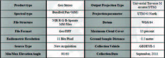
A fragment of raw stereo imagery from the Geoeye-1, a commercial satellite launched in 2008, over the barharly, Ahal velayat was taken September 2011. Two different types of imagery were provided: a low-resolution multispectral imagery (NIR/R/G/B) with 40cm GSD and a high resolution panchromatic imagery with 1.6m. Satellite imagery was taken in the 1 direction horizontally, divided into 6 models and covered by the pilot project areas (65km * 15km). Rational Polvnimial Coffecient(RPC) that provides geometry information of imagery was given when satellite imagery was taken. Imagery coordinate system and projection method were the same as GPS surveying result in the form of WGS84 datum and UTM projection method.
Image Processing
Image processing was implemented using modern development in Digital Photogrammetric Workstation (DPWs) and the ERDAS IMAGINE 10 and SOCET SET 5.6 module.
Table 1: Satellite imagery specification

Firstly, Pan-Sharpening was implemented throughout the ERDAS IMAGINE 10. In this process, a high resolutionpanchromatic imagery was combined with a relatively low resolution color multi spectral imagery to create high-resolution fused color imagery.This fused imagery provides a solution to identify the category of farms with clear color imagery.
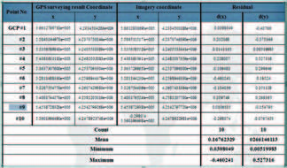
Table 2: Residual of GCPs result

After the Pan sharpening procedure, Aerial Triangulation (AT) was undertaken using the SOCET SET 5.6. As Rational Polynomial Coefficient (RPC) was roughly made of geometric correction, only particular adjustment was needed to carry out at the AT stage. In order to secure more positional accuracy, absolute orientation and interactive orientation were undertaken at the same stage using GCPs and tie points. Total 10 out of 12 GCPs was used to synchronized GCPs coordinate into imagery coordinate using interactive point measurement module, at least 2 GCPs was put into each model out of 6 models. Furthermore, around 250 tie points were automatically created, sometimes manually adjusted when there were unmatched tie points. These tie points were to make each model more tied each other and evenly distribute positional accuracy to the every model. Besides, check points obtained by Stop-And-Go techniques were inserted evenly at this stage in order to check residual error. The overall result of Aerial Triangulation (RMS) was satisfied at general accuracy. The Root Mean Square (RMS) was in easting(x)=0.2237, northing(y)=0.3497, elevation(z)=0.31307, and total RMS was computed as 0.5908.

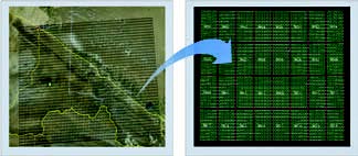
Figure 4: Map index
Digital Terrain Model (DTM) and True Orthophoto were generated to be loaded with land information management system. Firstly, the DTM was created to provide for surface information at the True Orthophoto generation stage because image-object reprojection was required to compensate for relief displacement. In this procedure, distances between easting(x) and northing(y) were set up as a 1m, and final format was a grid throughout adaptive strategy. After DTM production, True Orthophoto was generated for each model. At this time, the surface discontinuity caused by buildings was taken into account in the Ortho-rectification. This is because DTM was not able to delineate buildings. Hence, artificial features and buildings were collected as a feature data, and then some parts of displacement were rectified manually. Finally, each True Orthophoto models were merged throughout imagery mosaic module before it was embedded with the land information management system DB server.

Figure 5: Digital mapping result, cadastral map, topographic map
Mapping
Digital mapping was implemented using VR ONE 5.6, and the result was converted to DXF format and edited using the AUTOCAD 2O1O. The type of map was produced in the form of topography, and scale was 1:5000. In order to enhance the quality of map, digital mapping was undertaken in company with the stereo pairs instead of the True Orthophoto. Before digital mapping, index map and layers were set up. Firstly, sections between left upper corner E58° (Longitude), N39° (Latitude) and right lower corner E60°, N38° divided by 1° and then divided by 15’ once more as shown in the Figure 4. Among 32 sections resulting from division, each section was classified into 100 equal sections. A total 4 out of 32 sections were chosen to be utilized with respect to digital mapping.
In regards to layers, Layers were made based on topographic mapping; in the particular parcel layers were subdivided in order to extract digital cadastral map for the land registration. In this process, firstly satellite imagery was analyzed, and then layers that can be observed and described from the imagery were classified. After that, through discussion with the Ministry of Agriculture, layers supposed to be frequently used were determined and divided into 3 categories: Primary, sub-primary, sub-sub-primary structure. The primary structure was a total of 10 and composed of Roads, Building, Hydrograph, Boundary, Contour, Artificial feature, Border, Symbol, Text, and Index. Among these categories, basically most layers of Roads, Buildings, Hydrograph, Boundary, and Artificial features were incorporated into parcel layers.
The method of mapping was followed as applied in Turkmenistan. In particular, there was no discussion with concerned land users because most of the lands are owned by the government. For this reason, if there was issue, discussion was comprised between Korea Cadastral Survey Corporation and Land Resource Service. With regards to result of digital mapping, a total of 10,498 parcels were generated, and buildings were 21,408. As shown in the Figure 5, the left picture shows the digital mapping result, the upper right picture represents digital cadastral map extracted from digital mapping result, and the lower right picture shows topographic map in the form of SHP. After mapping process, parcel layers were edited to enclose lines, and were transformed into SHP format as a digital cadastral map before it was inserted into land information management system.
Land Information Management System Application
The land information management system was designed to register and manage digital cadastral map and land information resulting from parcel layers. This system can establish infrastructure as to provide reference data regarding taxation and national decision-making while the annual report is drafted. Before designing the system, Information strategic planning(ISP) was firstly implemented by anlyzing requirements and main tasks with concerned group working at the SLR. Consequently, information of rent, farming crops, gross production, residence derived from category of the annual report were main requirements in order to deal with resident and farming area information.

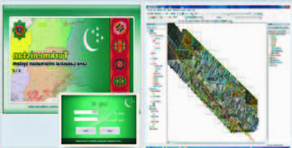
Figure 6: Turkmenistan Land information management system
Vector (topographic map, cadastral map) and attribute data (land information) were assigned to the DBMS. The method of system operation was that vector and attribute data were firstly loaded with the DB sever, and then they were managed and applied by users through operational laptop. DBMS was built up through Oracle 11g r1. The vector and attribute data were stored in the DBMS through ArcSDE and operated by users through Arc Desktop. The form of DXF for the vector data was transformed into SHP format and loaded with system because the system is based on Arc GIS, and Spatial Unit ID had to be automatically allocated to building and parcel.
When it comes to designing table of attribute data, arrtibutes extracted from category of the annual report and necessary functions analyed at the ISP stage were considered. Funciotns of user management and code management were designed for the basic configuration. Parcel and buildings were desinged to be newly registered and edited using the edit function; thus, shape and attribute of parcel were able to be edited and rectified using the edit function. Control points, SHP file, DXF file, and True Orthophoto were designed to be registerd using registration function. Serach and statistic function were designed in oder to calculate numeric data and identify parcel quickly. With regards to layers, parcel layers based on digital cadastral map as well as topographic layers were made up. ParcelInfo Feature Dataset concering digital cadastral map consists of parcel layers, building layres, control point and farming area layers. RegionInfo Feature Dataset consists of the state border layer, municipalaty border layer, block border layers, and is not able to be edited by users. TopoMap Feature Dataset consists of main rivers and roads. CAD Feature Dataset includes the original outcome in the form of DXF from digital mapping.
Qualitive & quantitive assessment
The positional accuracy of digital mapping was assessed and analyzed by comparing the check points coordinates obatined by the digital mapping and GPS-RTK. These check points were picked up in the 2 parts of the pilot project area where resident areas are largely composed of. The number of check points were around 250, and most of them were collected on the edge or corner of buildings. Around 70% of RMSe(x), and RMSe(y) were less than 1m, 20% were between 1m and 2m. On the whole, most of the points recorded excellent results only with satellite photogrammetric technique even though additional follow-up ground survey were not implemented. It can be assumed that the result was excellent considering satellite imagery resolution. These figures might be a problem in the case where cadastral map has to be produced to secure private land ownership. However, it turns out that land registration using satellite imagery could be an alternativ solution where land infomation management is more important than determining private land ownership like Turkmenistan, in particular considering the effectiveness of time and cost.
Conclusion
In Turkmenistan, the government owns and manage a whole nation’s land, and distribute a certain amount of land to each public in order to encourage agricultural farming and enhance productivity. As a result, land administration has focused on dealing with land information to generate reference data for taxation and national decision-making instead of securing and determining private land ownership.
Since a high positional accuracy is not crucial factor, the pilot project for land registraion and management using satellite photogrammetric technique that has relatively lower positional accuracy has been attempted. Hence, digital cadastral map was generated from digital mapping using satellite imagery, and land information management system was established based on vector and attribute data. This infrastructure enables users to manage and register land information through DBMS, and to gnerate reference data for taxation and national decision-making effectively.
References
Ahn K. and Song Y, 2011, Digital Photogrammetry for Land Registration in Developing Countries, FIG Working week 2011, Marrakech, Morocco
Alkan, M. and Solak, Y., 2010, An Investigation of 1:5000 Scale Photogrammetric Data for Cadastral Mapping Uses: A Case Study of Kastamonu- Taskopru, African Journal of Agricultural Research Vol. 5(18), pp. 2576-2588
AL-RUZOUQ R. And DIMITROV P., 2006, Photogrammetric Techniques for Cadastral Map Renewal, 13th FIG Congress, Munchen, Germany
Buckley S., Mills J., and Mitchell H., 2004, Improving the Accuracy of Photogrammetric Absolute Orientation using Surface Matching, The International Archives of the Photogrammetry, Remote Sensing and Spatial Information Sceiences, Vol. 34.
Harintaka, Subaryono, Susanto. A., 2009, Assessment of Low Cost Small Format Aerial Photogrammetry for Cadastral Mapping, 7th FIG Regional Conference, Hanoi, Vietanam
Rau J., Chen N., and Chen L., 2002, True Orthophoto Generation of Built-up Areas Using Multi-View Images, Photgrammetric Engineering & Remote Sensing Vol. 68, No. 6, June 2002, pp. 581-588
Siriba D., 2009, Positional Accuracy Assessment of a Cadastral Dataset based on the Knowledge of the Process Steps Used, 12th AGILE International Conference on Geographic Information Science
ZegheIu N., Photogrammetric Contribution to the Romanian Cadastre Development |


 (5.00 out of 5)


 (5.00 out of 5)


 (5.00 out of 5)


 (5.00 out of 5)
Leave your response!