| GNSS | |
Time-base accuracy evaluation of static, RTK, and PPK surveys in differential GNSS
Each procedure for static, PPK and RTK has its own advantages and short falls. |
 |
|
 |
|
 |
|
 |
|
Abstract
The Differential Global Positioning System (DGNSS), have three types of observations Static, Post processed Kinematics (PPK) and Real-Time Kinematic (RTK) focuses on real-world efficiency-accuracy trade offs. In “time-based survey methodology” in GNSS applications, particularly focusing on accuracy and efficiency for India. In DGNSS surveying methods that rely on the timing of satellite signals and observations achieve high positional accuracy which is time dependent. To confirm the most accurate methods, DGNSS observations were taken using the three methods by fixing a base station, Rover station. Also, the different time of observation is considered to focus on accuracy and efficiency. It has been inferred for all the GNSS surveying procedures, the correction of all skills, that help to accomplish high positional accuracy. Static surveying is time-consuming but of high performance, whereas PPK rectifies errors after data collection, RTK provides positional perfections in real-time. Selecting an observational procedure shall offer empirical accurate data for surveyors to enhance fieldwork procedures. However, the time-based evaluation (30 minutes vs 1-hour static data showed an error difference of <=0.12”) is particularly valuable for resource-constrained projects. However, broader applicability requires deeper statistical validation.
1. Introduction
Capturing 3D geospatial information, the foundation data should be fast, accurate, comprehensive, reliable, cost-effective etc. The large-scale (1:1,000 or 1:500) topographic data is presently widely used for cadastral or town planning surveys. For 3-D formation, the Digital Elevation Model (DEM) data (50cmX50cm grid with 10cm vertical accuracy) can be used. Contours having an interval of 1cm, Orthophotos at 5-10cm ground sampling distance (GSD) and GIS layers considered as per Amrut of 290 layers. The present practice of capturing data is redundant, dissimilar, disconnected, done in silos, dissimilar, poor in scale, coverage and incomplete so for one data multiple surveys are conducted. It is pertinent to have one survey that should be unanimously applied and should be realistic and good (Specht, 2023). The orthodox method of data capturing is done by using total station, GNSS, Satellite imageries and drone photographs but these are unsuitable as cannot be applicable in inaccessible terrain, remote areas, erroneous, inaccurate, Time-consuming, uneconomical, inaccurate etc. da. Silva et al., (2025).
There are numerous Satellite Navigation (SATNAV) systems operating around the world. Some are global and others only provide service within a certain region. The term Global Navigation Satellite System (GNSS) is defined as the collection of all SATNAV systems and their augmentations. The various SATNAV systems are the U.S. Global Positioning System (GPS), the European Galileo system, the Russian Federation Global Navigation Satellite System (GLONASS), the Chinese BeiDou Navigation Satostellation Elite System (BDS), India’s Navigation with Indian Constellation (NavIC), and Japan’s Quasi-Zenith Satellite System (QZSS). Each system operates with enhanced accuracy and reliability. By triangulating signals from multiple satellites, GNSS receivers can have better coordinates within meters or centimetres accuracy (Walker et al, 2020, Nanda et al, 2023, Ramiro et al, 2025).
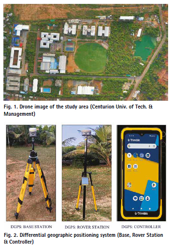
These satellite-based systems provide accurate positioning, navigation, and timing to users around the globe, enabling a wide array of applications across various sectors. Originally developed for military purposes, GNSS has become integral to civilian life, influencing everything from everyday navigation in vehicles to precision agriculture, aviation, and disaster response (Steuer et al., 2025). The GNSS used as it is having accurate navigation (10-20cm), weather independent, worldwide coverage, no line of sight needed, high geodetic Accuracy, 24-hour operation, quick and economic, a common coordinate system, a wide range of applications, competitively priced, and accessible for both civilian and military (Shi et al, 2020, Nanda et al, 2024, Popove et al, 2025; Preety et al., 2022) The comparison of the 3-survey methods Static, PPK and RTK along with drone image of the area of CUTM (Atik et al. 2025) are applied which is given in Table-1.
GNSS: Hence GNSS as an innovative technique in modern surveys as location tracking, enhances safety in transportation, and supports emergency services, like autonomous vehicles and drone operations.
Furthermore, GNSS plays a crucial role in scientific research, environmental monitoring, and telecommunications. Whether navigating city streets or conducting complex scientific measurements, GNSS remain at the forefront of modern navigation solutions (Vetrella et al, 2016, Li et al., 2025, Weng et al, 2025; Chillab et al., 2023).
Geographical Positioning System: (GPS): GNSS is an aligning arrangement of a network of satellites that uninterruptedly transmit coded information. The transmitted information is received by receivers to exactly recognize locations on Earth by measuring distances from the satellites (Kim et al, 2017; Gao et al, 2023).
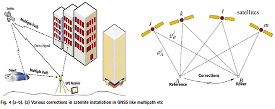
The Global Positioning System (GPS) is a U.S.-maintained usefulness that provides users with positioning, navigation, and timing (PNT) services. The GPS is composed of three main segments: the Space Segment, the Control Segment, and the User Segment. The Space Segment consists of GPS satellites orbiting Earth, the Control Segment manages and monitors those satellites, and the User Segment comprises GPS receivers that receive signals from the satellites to determine the location.
GPS has many advantages over Traditional Terrestrial Surveying Techniques which rely on line of sight between the survey instrument and a target with high geodetic accuracy, indiscriminate reception place, three dimensional and free. On the existence of obstructions, the survey work can be carried out by traverse method. GPS is widely used for navigation, mapping, and tracking, but it does have a few limitations i.e. Signal obstruction (urban canopy, Dense Forests and Tunnels, Indoor), heavy rain, solar storms, Electronic Interference, Jamming and Spoofing. GPS adds to the advanced framework in blockchain, the Internet of Things ( IoT) and artificial intelligence (AI), in emergency handling and public safety arrangements, (Mekik et al, 2009; Majumdar et al, 2025)
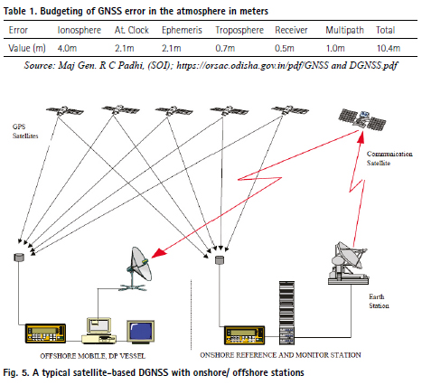
Sources of error in GNSS: The errors incorporated in the GNSS system are Satellite errors (orbit uncertainty and satellite clock model), Receiver errors (Receiver clock and noise), observation errors (Ionospheric delay and Tropospheric delay) and station errors (station co-ordinates, Signals effect error and multipath). To avoid these large cumulative errors, the Differential GPS/GNSS is incorporated (IIRS – E book- 2023).
DGNSS: The GNSS is available globally and free to use by civilians, without any cost. Some errors are incorporated into the information by single point positioning due to satellite clock error, orbital error, ionospheric delay, tropospheric delay, receiver clock error and partial multipath error. These errors can be purged by the Differential Global Navigation Satellite System (DGNSS). DGNSS is an enhancement of standard GNSS, which has improved accuracy, integrity, and reliability by using a network of f ixed ground-based reference stations.
GNSS addresses the drawbacks by using ground-based reference stations, also known as base stations, and that broadcast correction to GNSS signals with position accuracy (Krasuski et al, 2021; Bakul et al, 2022; Spchet, 2023)
These reference stations are positioned at precisely known locations. They monitor uninterruptedly the GNSS received signals and calculate the errors in those signals. The error information is then transmitted to DGNSS-enabled rover receivers in the field. DGNSS. These instruments often consist of a GNSS receiver, a data processing unit to apply the corrections, and a communication link to receive the correction data from the reference station (Table 1).
Advantages/disadvantages of DGNSS: The advantages of DGNSS are increased positioning Accuracy, offering centimetre level precision, popularity and, wide availability, Real-time Positioning: Many DGNSS systems provide real-time corrections, high-accuracy positioning for time-sensitive applications, Enhanced Reliability in data positioning data and versatile applications (Pretty et al, 2022; Chilab et al, 2023). The disadvantages of DGNSS are requiring correction Signal, being unavailable in remote or obstructed areas, increased initial equipment Cost, the potential for signal interference, limited range, and complexity (Biswas et al, 2022). The GNSS survey includes testing different positioning surveys can be of two types static and Kinematic in GNSS (Dardanelli et al, 2021; Alkan et al, 2025).
Time-Based Surveying with DGNSS: The time of the extent is the receiver time of the acknowledged signals. The accuracy in receiving satellite information the timing is critical. They should maintain correct time called real time and differential correction is to be incorporated to get the most processed information. The surged accuracy improves to 1-3cm from 15m in the case of Single point positioning by GNSS is 3-5m. and can have applications in the case of land surveys, and geodetic and hydrographic surveys. They can also be used for structural health monitoring, precession farming and disaster monitoring like earthquakes, Volcanic eruptions, landslides, etc (SOI 2009).
Pseudo Range (PR): The PR (in meters) is the distance between the receiver antenna and the satellite antenna together with receiver and satellite clock offsets including atmospheric delays. Mathematically; PR = distance + c(receiver clock offset − satellite clock offset + other biases) so that the PR reflects the real-time (stored in m) behaviour of the receiver and satellite clocks. Where, the measured range between the satellite and receiver.
Distance: True geometric distance between the satellite and the receiver, Velocity ( C ) is the Speed of light (299,792,458 meters per second (m/s), Receiver clock offset (error in receiver’s time). Satellite clock offset (error in satellite’s time). The other biases: Include ionospheric delay, tropospheric delay, multipath errors, hardware delays, etc.
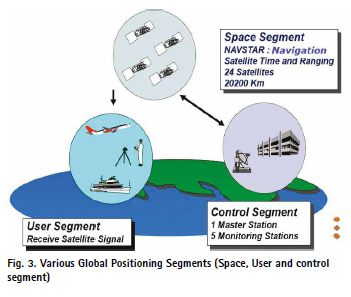
Parts of DGNSS: For the DGNSS survey, we need a minimum of two receiver antennae, one is for Base Station and one or more Rover Station. The various components are GNSS Satellites (A constellation of satellites orbiting Earth, transmitting signals for location determination), Base Station (Reference Station), Rover Receivers (A mobile GNSS receiver used in the field to control position, receiving satellite signals and correct data) (Fig 3). Communication Link, and Data Processing Unit: Hardware or software in the rover that applies the corrections received from the base station to improve the accuracy of its position. Antennas, power supplies, soft wares for all stations/rovers, data storage and mounting equipment used for fixing.
Why DGNSS: The absolute position determination with GNSS is less accurate than relative positioning between two stations. Error sources in GNSS locations include the strata in the atmosphere, satellite problems, and the receiver. These errors can introduce delay and distortion GNSS signals, that affect the accuracy and efficiency. These acting errors (biases) where the error occurs are of three categories: i. Errors related to distance: mainly ephemeris and propagation errors, are nearly the same for neighbouring stations, as long as they are sufficiently close, and hence disappear in the differences. ii. Errors related to time: are coped with by synchronized or nearly simultaneous observations. iii. Uncorrelated errors : affect both participating stations and need a calibration.
Corrections in DGNSS: The reference station commonly calculates pseudo range corrections (PRC) and range rate corrections (RRC) which are transmitted to the remote receiver in real-time. The remote receiver applies the corrections to the measured pseudo ranges and performs point positioning with the corrected pseudo ranges. The use of the corrected pseudo ranges improves the position accuracy concerning the base station.
The Applications OF DGNSS: are precision agriculture (Guiding tractors for precise planting, spraying, and harvesting, optimizing crop yields and reducing resource waste), construction surveying (for accurate positioning for construction layout, ensuring buildings and infrastructure are built according to design specifications, Hydrographic Surveying: Marine Navigation, Aviation, Mapping underwater ( navigation, dredging, and coastal zone management). The other applications are geographic Information Systems (GIS): Autonomous Vehicle Navigation, etc. (Gleason, 1996).
Objectives: There exist three types of DGNSS surveys. The objective of the work is to find out.
i. The Basic ideas about DGNSS (Differential global navigation satellite system)
ii. To find out the accuracy of three types of survey(Static, PPK and RTK)
iii. To find the accuracy obtained based on the timing of observations. 3.
3. Methodology
Data Collection & Processing Timing Requires long observation times (minutes to hours, depending on baseline length and required accuracy) and all data processing happens in the post-processing stage. The receiver remains stationary for the entire observation. Provides real time centimetre-level accuracy by static and PPK method of survey. Collects raw GNSS data at both the base station and rover. No real-time communication is involved during the observation phase. The base station data is downloaded later for post-processing. All data processing occurs post-mission using specialized software. The rover receives corrections from a base station via a radio link and calculates its position on-the-fly, during the data collection process in RTK. It May or may not require static initialization, depending on the specific RTK approach. RTK requires a continuous, reliable radio/ cellular data link to transmit corrections from the base station to the rover in real time for base station communication.
Methodology For Static Survey: Static GNSS (Global Navigation Satellite System) surveying is a precise technique used in geodesy, engineering, and cadastral applications to determine accurate positions by collecting data over long observation periods. It involves Setup for Site Selection and includes a location with a clear, unobstructed view of the sky for optimal satellite signal reception. Avoid areas near tall buildings, under tree canopies or foliage, inside buildings or under roofs, and the power lines for better accuracy of points. The survey started with Trimble access being connected with the base and rover station. After completion of the survey, all information/ data are backed up for later processing by Trimble Business Center. (TA: Trimble Access software and Trimble Business Centre ).
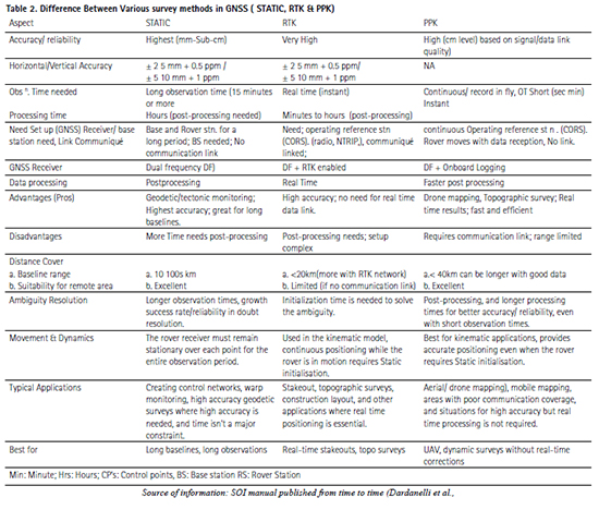
Methodology For PPK Survey : PPK (Post-Processed Kinematic) GNSS surveying is a technique that allows for high-accuracy positioning by recording GNSS data at both a base station and a rover, then correcting the rover’s positions after the survey using post-processing software. The base station records GNSS data at a known location. Rover (mobile receiver) collects data at unknown positions (e.g., UAV flight paths or land points). After data collection, the rover’s data is corrected using the base station’s data in post processing software, correcting for satellite and atmospheric errors. Unlike RTK, it doesn’t require a real-time link. After f ieldwork, data from both is processed together to apply differential corrections. PPK is robust against signal interruptions and works over longer distances. Although post-processing is needed, it’s ideal for high-precision applications where real time accuracy isn’t critical. This makes it suitable for aerial surveys, mapping, and challenging environments.
There requirement for uninterrupted site selection, proper levelled and stable base station set up, and Rover set up with a well-connected receiver, antenna, and data collector. The set-up must have a proper power connection and data collector system. The completion of the survey all information/ data are backed up and start processing (Shao et al. 2015; Cirillo et al., 2022; Chao et al. 2023). Various applications of PPK survey are Various application of PPK survey are Land and topographic surveys, Construction (a) (c) (b) (d) Static, PPK (Post processed kinematics) and RTK (Realtime kinematics) site layout, Aerial mapping by drones, pipeline and utility surveys and Monitoring earthworks and infrastructure projects.
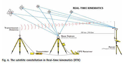
B.RTK SURVEY: RTK (Real-Time Kinematic) survey is a DGNSS technique providing centimetre-level accuracy in real time. A base station transmits corrections to a rover, enabling instant, precise positioning. It requires a constant communication link, typically radio, between the base and the rover. RTK is efficient for surveying and construction needing immediate results. However, its performance depends on signal strength and short distances. Obstructions can degrade accuracy, but its speed and precision are valued for many tasks.
The applications are Land Surveying (Boundary mapping, property surveys, and topographical surveys, Construction: Site layout, road alignment, and excavation control, Agriculture: Precision farming, planting, and irrigation layout, Aerial Mapping: Used with drones to geotag images for photogrammetry, and Utilities and Infrastructure: Pipeline and utility alignment surveys.
The appraisal among the three methods of DGNSS survey applications by Static, PPK (Post processed kinematics) and RTK (Realtime kinematics) in GNSS Survey is in Table 2.
DOP and PDOP in Satellite Navigation: In satellite navigation (like GPS), DOP (Dilution of Position) and PDOP (Position Dilution of Precision) are numerical values that measure the quality of the geometry (3-D) for visible satellites disturbs the precision of the fixed position whereas DOP accesses the impact of satellite geometry on position precision. The lower value of PDOP indicates better satellite geometry and more accurate positioning. The DOP value 1 is ideal. In India it is accepted a PDOP value of 2-4 has accurate positioning with good satellite geometry and a higher value (>7) has weak satellite geometry and the positioning is not reliable as per European GNSS Glossary 2018, (Cui et al, 2021; Susi et al. 2023; Jing et al, 2025)
Equipment needed for Base Rover GPS: The DGNSS equipment used in the study of TRIMMBLE and RTK observation is the GPS base station, GPS rover(s) and the communication link between the base and the rover(s). The GPS base station and each GPS rover must contain: (i) a GPS receiver, (ii) a GPS antenna (iii) a Communication link (Radio and radio antenna or cell phone), a Survey Controller (Real-time surveys must have a controller at the rover receiver) and Power supply (AC power supply or portable batteries) along with the Appropriate cabling.
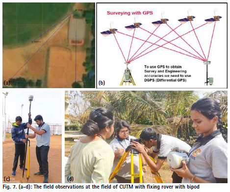
FIELDWORK: Four locations were practical to work. We measure these four points with DGNSS in STATIC mode for one hour, STATIC mode for 30 minutes, RTK mode for 10 minutes, and PPK mode for 10 minutes. Then we process the data in TBC (Trimble Business Centre). We put the known co-ordinate in Base Station co-ordinate then process the baseline accompanying others processing and print the map.
4. Results
Each procedure for static, PPK and RTK has its own advantages and short falls. Results are for different methodologies has been verified for each processes and documented for their appropriate use. Selecting an observational procedure shall offer empirical accuracy. The observational results are in list 1 and list 2.
5. Discussion
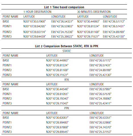
The difference between the coordinates of those points is:
i. The coordinates of the Base station in one-hour observation are N20°10’30.57900″ Lat. & E85°42’26.54327″ Long. and in 30 minutes observation is N20°10’30.44993″ Lat. & E85°42’26.57772″ Long. The difference between the two latitudes is 00°00’00.12907” second and Longitude -00°00’00 .3445”. The difference is very minimal.
ii. The coordinates of Point 1 in one hour observation is N20°10’28.94265″ Lat. & E85°42’26.53903″ Long. And in 30 minutes observation is N20°10’28.81324″ Lat. & E85°42’26.57431″ Long. The difference between the two coordinates is
iii. The coordinates of Point2 in one hour observation is N20°10’28.92774″ Lat. & E85°42’24.75236″ Long. And in 30 minutes observation is N20°10’28.81169″ Lat. & E85°42’24.89789″ Long. The difference between the two latitudes is 00°00’00.11605” second and Longitude -00°00’00.14553”. The difference is very minimal.
iv. The coordinates of Point 3 in one hour observation is N20°10’29.84439″ Lat. & E85°42’25.38622″ Long. And in 30 minutes observation is N20°10’29.71527″ Lat. & E85°42’25.42130″ Long. The difference between the two latitudes is 00°00’00.12912” second and Longitude -00°00’00.3508”. The difference is very minimal.
The difference in the coordinates in latitude and longitude is minimal in fractions of a second which can be neglected. The difference between the coordinates of these three points in STSTIC RTK & PPK mode are
a. The coordinates of a Base station in STATIC observation is N20°10’30.44993″ Lat. & E85°42’26.57772″ Long. In RTK observation is N20°10’30.44546″ Lat. & E85°42’26.57997″ Long. In PPK observation is N20°10’30.63007″ Lat. & E85°42’26.53351″. The difference is very minimal.
b. The coordinates of Point1 station in STATIC observation is N20°10’28.81324″ Lat. & E85°42’26.57431″ Long. In RTK observation is N20°10’28.81055″ Lat. & E85°42’26.57578″ Long. In PPK observation is N20°10’28.99480″ Lat. & E85°42’26.52866″. The difference is very minimal.
c. The coordinates of Point1 station in STATIC observation is N20°10’28.81169″ Lat. & E85°42’24.89789″ Long. In RTK observation is N20°10’28.79340″ Lat. & E85°42’24.78890″ Long. In PPK observation is N20°10’28.97888″ Lat. & E85°42’24.74370″. The difference is very minimal.
d. The coordinates of Point1 station in STATIC observation is N20°10’29.71527″ Lat. & E85°42’25.42130″ Long. In RTK observation is N20°10’29.71043″ Lat. & E85°42’25.42411″ Long. In PPK observation is N20°10’29.89545″ Lat. & E85°42’25.37753″. The difference is very minimal.
The comparison of DGNSS static survey coordinates with one-hour versus 30-minute observation times reveals minimal discrepancies. Latitude differences range from 0.116″ to 0.129″, while longitude differences span -0.146″ to -0.353″. This consistency suggests that reducing the observation time to 30 minutes may be viable in similar conditions without significant loss of accuracy. However, this depends on factors like satellite geometry, atmospheric conditions, equipment, and the desired accuracy. Further investigation is advised to confirm this finding for broader applicability. A shorter duration will save on field time and resources (Mc, Mohan et al 2021; Zhang et al. 2024).
Coordinate comparisons between Static, RTK, and PPK DGNSS methods reveal “very minimal” differences. While all provide reasonable consistency, the choice depends on project needs. Static offers the highest accuracy, RTK balances speed and precision, and PPK suits environments lacking real-time links. Variations reflect method-specific error characteristics and factors like atmospheric conditions. Project tolerances must guide method selection. Acknowledging these minimal differences remains crucial in ensuring appropriate application and data reliability. Analysis preprints highlighting the different problems and challenges allied with the GNSS receivers. It’s appropriate to use and best combination to receive accurate and exact data (Diouf et al. 2024).
6. Conclusion
In summary, DGNSS observation time tests (30 vs. 60 minutes) showed minimal coordinate differences, suggesting reduced times may be viable. Comparing Static, RTK, and PPK methods also revealed “very minimal” differences, yet method selection depends on project needs. Static offers the highest accuracy, RTK balances speed and precision, and PPK is suited to environments lacking real-time communication links. Key factors influencing accuracy include atmospheric conditions, satellite geometry, and equipment. Acknowledging and understanding method-specific error characteristics remains crucial for reliable data.
In the DGNSS survey, more time can provide more accuracy in STATIC mode. And STATIC, RTK & PPK mode has different usages and different advantages. The results in the case of various methods of DGNSS Survey are:
• Static: Best for high-precision control over long distances and non-time-sensitive applications.
• PPK: Ideal for mobile mapping or UAV surveys where real-time corrections are not available.
• RTK: Best for real-time applications in the short-to-medium range, such as construction, Topo surveys, and precision farming.
Disclaimer (Artificial Intelligence)
Author(s) hereby declare that NO generative AI technologies such as Large Language Models (ChatGPT, COPILOT, etc) and text-to-image generators have been used during writing or editing of this manuscript.
Acknowledgement
We acknowledge commending works to the students, Mr Ayan Mondal, Mr Rohan Roy, Miss Bandana Acharya, Miss Tanushree Mondal, Miss Anwesha Ghosh, and Miss Maitri Dhibar in helping during field observations.
Competing Interests
Authors have declared that no competing interests exist.
References
Alkan, R. M., Erol, S., Mutlu, B., & Bıyık, M. Y. (2025). Investigation of static and kinematic surveying performance of handheld GNSS receiver. Engineering Proceedings, 88(1), 24. https://doi.org/10.3390/engproc2025088024
Atik, M. E., Arkali, M., & Atik, S. O. (2025). Impact of UAV-derived RTK/ PPK products on geometric correction of VHR satellite imagery. Drones, 9(4), 291. https://doi.org/10.3390/drones9040291
Bakuła, M., Uradziński, M., & Krasuski, K. (2022). Performance of DGNSS smartphone positioning with the use of P(L1) vs. P(L5) pseudo-range measurements. Remote Sensing, 14(4), 929. https://doi.org/10.3390/rs14040929
Biswas, T., Banerjee, P., & Paul, A. (2022). Impact of low-latitude ionospheric effects on precise position determination. Radio Science, 57(4). https://doi.org/10.1029/2021RS007322
Chillab, R. K., Jaber, A. S., Smida, M. B., & Sakly, A. (2023). Optimal DG location and sizing to minimize losses and improve voltage profile using Garra rufa optimization. Sustainability, 15(2), 1156. https://doi.org/10.3390/su15021156
Cho, J. M., & Lee, B. K. (2023). GCP and PPK utilization plan to deal with RTK signal interruption in RTK-UAV photogrammetry. Drones, 7(4), 265. https:// doi.org/10.3390/drones7040265
Cirillo, D., Cerritelli, F., Agostini, S., Bello, S., Lavecchia, G., & Brozzetti, F. (2022). Integrating post-processing kinematic (PPK)–structure from-motion (SfM) with unmanned aerial vehicle (UAV) photogrammetry and digital field mapping for structural geological analysis. ISPRS International Journal of Geo-Information, 11(8), 437. https://doi.org/10.3390/ijgi11080437
Cui, H., & Zhang, S. (2021). Satellite availability and service performance evaluation for next generation GNSS, RNSS and LEO augmentation constellation. Remote Sensing, 13(18), 3698. https://doi.org/10.3390/rs13183698
da Silva, I., Segantine, P. C. L., & Poleszuk dos Santos Rosa, G. (2025). Global Navigation Satellite System: GNSS. In Geomatics Applied to Civil Engineering. Springer, Cham. https:// doi.org/10.1007/978-3-031-75737-2_17
Dardanelli, G., Maltese, A., Pipitone, C., Pisciotta, A., & Lo Brutto, M. (2021). NRTK, PPP or static, that is the question. Testing different positioning solutions for GNSS survey. Remote Sensing, 13(7), 1406. https://doi.org/10.3390/rs13071406
Diouf, D., Sall, O., Gueye, I., & Ndiaye, F. (2024). Performance evaluation of low cost dual frequency GNSS receivers for precise positioning in Senegal: Issues & challenges. Journal of Analytical Sciences, Methods and Instrumentation, 14, 23–37. https://doi.org/10.4236/jasmi.2024.1420
Gao, M., Meng, Z., Zhu, H., Xu, A., Cao, Z., & Tan, C. (2023). Research on the real-time ambiguity resolution algorithm of GNSS/Galileo/BDS based on CNES real-time products. Remote Sensing, 15(21), 5159. https://doi.org/10.3390/rs15215159
Gleason, D. M. (1996). Avoiding numerical stability problems of long duration DGNSS/ INS Kalman filters. Journal of Geodesy, 70, 263–275. https://doi.org/10.1007/BF00867347 Indian Institute of Remote Sensing, ISRO. (2023). Overview of Remote Sensing & GIS Applications. E-Book, April 2023
Jing, D., Li, W., Han, L., Li, X., Li, L., Zhang, Y., Guo, L., & Xing, M. (2025). A fast satellite selection algorithm based on hierarchical clustering and iterative subset optimization. Remote Sensing, 17(5), 853. https://doi.org/10.3390/rs17050853
Kim, J., Song, J., No, H., Han, D., Kim, D., Park, B., & Kee, C. (2017). Accuracy improvement of DGNSS for low-cost single-frequency receiver using modified Flächen Korrektur parameter correction. ISPRS International Journal of Geo-Information, 6(7), 222. https://doi.org/10.3390/ijgi6070222
Krasuski, K., Popielarczyk, D., Ciećko, A., & Ćwiklak, J. (2021). A new strategy for improving the accuracy of aircraft positioning using DGNSS technique in aerial navigation. Energies, 14(15), 4431. https://doi.org/10.3390/en14154431
Majumdar, S., & Awasthi, A. (2025). From vulnerability to resilience: Securing public safety GNSS and location services with smart radio, blockchain, and AI-driven adaptability. Electronics, 14(6). https:// doi.org/10.3390/electronics14061207
McMahon, C., Mora, O. E., & Starek, M. J. (2021). Evaluating the performance of sUAS photogrammetry with PPK positioning for infrastructure mapping. Drones, 5(2), 50. https://doi.org/10.3390/drones5020050
Mekik, C., & Arslanoglu, M. (2009). Investigation on accuracies of Real Time Kinematic GNSS for GIS applications. Remote Sensing, 1(1), 22–35. https://doi.org/10.3390/rs1010022
Nanda, R. N., Mishra, S. P., & Barik, K. K. (2024). Smart city eco system management – Necessity of map compilation and generalization on Indian Integrated Geospatial Information Framework (IGIF). African Journal of Biological Sciences, 6(5), 3181– 3204. https://doi. org/10.33472/AFJBS.6.5.2024.3181-3204
Nanda, R. N., Mishra, S. P., Mishra, S. P., Barik, K. K., & Sethi, K. C. (2023). Review of episodic voyage of engineering surveying and cartography in India. CJAST, 42(12), 32–48. https://doi.org/10.9734/CJAST/2023/v42i124109
Popov, P., Mihailov, M. E., Dutu, L., & Andrescu, D. (2025). Enhancing maritime navigation: A Global Navigation Satellite System (GNSS) signal quality monitoring system for the north western Black Sea. Atmosphere, 16(5), 500. https://doi.org/10.3390/atmos16050500
Preety, K., Prasad, A. K., Varma, A. K., & El Askary, H. (2022). Accuracy assessment, comparative performance, and enhancement of public domain digital elevation models (ASTER 30 m, SRTM 30 m, CARTOSAT 30 m, SRTM 90 m, MERIT 90 m, and Tan-DEM-X 90 m) using DGNSS. Remote Sensing, 14(6), 1334. https://doi.org/10.3390/rs14061334
Ramiro, H., Gamallo-Palomares, Ó., Junquera Sánchez, J., & Gómez-Sánchez, J. A. (2025). Time to first fix robustness of Global Navigation Satellite Systems: Comparison study. Sensors, 25(5), 1599. https://doi.org/10.3390/s25051599
Shao, M., & Sui, X. (2015). Study on differential GNSS positioning methods. In 2015 International Conference on Computer Science and Mechanical Automation (CSMA) (pp. 223 225).https://doi.org/10.1109/CSMA.2015.51
Shi, C., & Wei, N. (2020). Satellite navigation for digital Earth. In Guo, H., Goodchild, M. F., & Annoni, A. (Eds.), Manual of Digital Earth. Springer, Singapore. https:// doi.org/10.1007/978-981-32-9915-3_4
Specht, C. (2023). Maritime DGNSS system positioning accuracy as a function of the HDOP in the context of hydrographic survey performance. Remote Sensing, 15(1), 10. https://doi.org/10.3390/rs15010010
Steuer, M., Burdzik, R., & Piednoir, F. (2025). Implementation of Global Navigation Satellite Systems in railway traffic control systems: Overview of navigation systems, application areas, and implementation plans. Applied Sciences, 15(1), 356. https://doi.org/10.3390/app15010356
Survey of India. (2009). Handbook of Topography, Chapter III, corrected up to 2009. Control by GNSS & Triangulation / Trilateration, 1–50. K., & Fernandez-Hernandez, I. (2023). Assessing the high-accuracy service at high latitudes. Engineering Proceedings, 54(1), 8. https://doi.org/10.3390/ENC2023-15421
Trimble Inc. TA: Trimble Access software and TBC: Trimble Business Center software.
Walker, J., & Awange, J. (2020). Global Navigation Satellite System. In Surveying for Civil and Mine Engineers. Springer, Cham. https://doi.org/10.1007/978-3-030-45803-4_14
Zhang, Q., Zhang, L., Sun, A., Meng, X., Zhao, D., & Hancock, C. (2024). GNSS carrier-phase multipath modelling and correction: A review and prospect of data processing methods. Remote Sensing, 16(1), 189. https://doi.org/10.3390/rs16010189
Disclaimer/Publisher’s Note:
The statements, opinions and data contained in all publications are solely those of the individual author(s) and contributor(s) and not of the publisher and/or the editor(s). This publisher and/ or the editor(s) disclaim responsibility for any injury to people or property resulting from any ideas, methods, instructions or products referred to in the content.
The paper originally published in Advances in Research Volume 26, Issue 3, Page 489-502, 2025; Article no.AIR.137248 ISSN: 2348 0394, NLM ID: 101666096 and may be cited as Mishra, Siba Prasad, Kamal Kumar Barik, Rabindra Nath Nand, and Kumar Ch. Sethi. 2025. “Time-Base Accuracy Evaluation of Static, RTK, and PPK Surveys in Differential GNSS”. Advances in Research 26 (3):489-502. https://doi.org/10.9734/air/2025/v26i31365.
© Copyright (2025): Author(s). The licensee is the journal publisher. This is an Open Access article distributed under the terms of the Creative Commons Attribution License (http://creativecommons.org/licenses/by/4.0), which permits unrestricted use, distribution, and reproduction in any medium, provided the original work is properly cited.
The paper is republished with authors’ permission


 (No Ratings Yet)


Leave your response!