| GNSS | |
Integrating GPS/INS/PL for Robust Positioning
|
||||
|
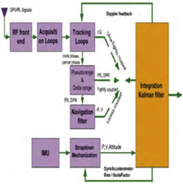
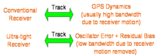
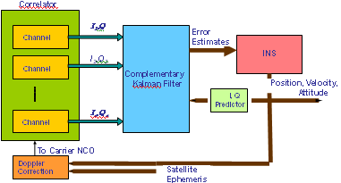
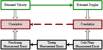
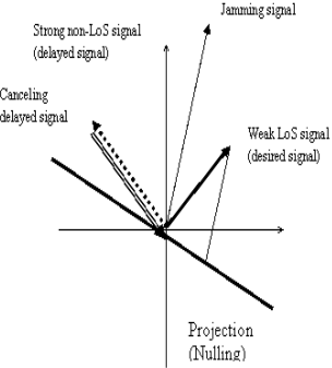
Introduction Inertial Navigation Systems (INS) are based on accelerometers and gyroscopes for position and attitude determination. Thus, INS is self-contained and autonomous. This makes INS an optimal option to be integrated with GPS, as both systems can complement each other to enhance positioning performance (Greenspan, 1996). On the one hand, the advantages of INS include high positioning (and attitude) update rates, and high short-term accuracy, both helpful in bridging the signal gaps between the GPS signal sampling epochs and the gaps due to signal outages. On the other hand, however, a major drawback of INS when operated as a stand-alone system is the time-dependent growth of systematic errors, which can be calibrated by GPS ranging measurements with consistent accuracy. Over the past three decades, the following three modes for GPS/INS integration have been identified (Alban et al., 2003): * Loose integrations In the loose integration mode, both GPS and INS are treated as independent navigation sensors and thus, a decentralized filtering strategy is used (Cunningham & Lewantowicz, 1988). GPS raw measurements are pre-analysed via a local (GPS) Kalman filter to produce the so-called GPS position and/or velocity information, which are then used to update the master (INS) filter for calibrating the INS errors and producing position, velocity and attitude information to users. However, one of the major drawbacks of the this early integration mode is that, when number of the tracked GPS satellites drops to fewer than four, GPS aiding of the INS is essentially disabled. More recently, the tight integration mode has been the major research focus (e.g., Farrel and Barth, 1999; Grejner-Brezinska et al., 1998; Wang et al., 2000). In this mode, a centralized filtering strategy is utilized to process raw GPS and INS measurements. The raw GPS measurements are directly used as the update measurements in the single filter for the INS instrument calibration and navigation. This integration mode is much better than the loose integration mode. Both the system level (loosely-coupled) and sensor level (tightly-coupled) architectures have been developed to demonstrate the robustness of the integrated system (Farrell & Barth, 1998; Greenspan, 1996). These integrated systems provided several advantages over the individual systems (e.g., Farrell & Barth, 1998). However, two primary drawbacks still remained: a) the integrated system is still vulnerable to problems caused by platform dynamics; and b) the receiver measurements that are used in the integration filter are correlated. In the former case, when the receiver dynamics exceed a certain threshold, the receiver loses lock on the GPS signals. A sustained signal loss that exceeds the INS bridging level will result in the INS functioning in the ‘free-inertial’ mode, where error growth with time seriously degrades system performance. In the latter case, the state vector of the integrated Kalman filter (KF) can be augmented to account for the correlations, but this increases the overall computational complexity. In addition, these conventional tight integration modes are far from optimal in terms of weak signal tracking and interference suppression, which are critical in robust positioning. The ultra-tight integration of GPS/INS has attracted more and more attention over the past few years, because this integration mode can fully exploit the potential capabilities of each system and combine them in an optimal way, more effectively addressing challenging issues of positioning availability and reliability (e.g., Greenspan, 1996; Sennott & Senffner, 1997). Compared with both loose and tight integration modes, one of the major advantages of the ultra-tight integration is more robust satellite tracking, offering a more resistance to radio interferences and multipath noise. Although GPS/INS integration can perform well even when few than four GPS satellites are being tracked, the low quality of the measurements and the undesirable geometry may significantly degrade the system performance. This issue can be effectively addressed with the inclusion of ground-based GPS-like transmitters – pseudo-satellites or pseudolites, which can be easily installed wherever they are needed. They therefore offer great flexibility in the augmentation of GPS/INS applications. In the early 1990s, researchers at Stanford University developed a low cost GPS L1 C/A code pseudolite. Due to the potential of the pseudolite applications in ubiquitous positioning, both theoretical and experimental research has been intensified over the past decade (Wang, 2002). A new integration concept to include pseudolites into the tightly integrated GPS/INS system has been proposed and tested (Wang et al., 2001). Experimental studies on this concept have demonstrated potential benefits of the tight integration of GPS/INS/Pseudolites in terms of accuracy and reliability (Dorota et al., 2002; Lee et al. 2002). The integration concept of GPS/INS/Pseduolites has been further developed into the potentially highest level – ultra-tight integration, with the aid of smart antennas enhancing the weak signal tracking and inference resistance (Babu and Wang, 2004; Li and Wang, 2005; Chan et al., 2005). This paper presents an overview of the ultra-tight integration, the features and performance of a variety of ultra-tight integration scenarios. Various challenging issues of the ultra-tight integration are discussed. Development of Ultra-Tight Integration of GPS/INS/PLAlthough the concept of ultra-tight integration and its advantages were published as early as in 1975 (Cox, 1982), nevertheless the system did not become popular due to the complexities involved in designing and implementing such a system 1980s. The early 21st century has witnessed an increased interest and research activities in the area of the ultra-tightly integrated systems to address the aforementioned problems. The principal advantage of this integrated system is that a Doppler frequency derived from the INS is integrated with the tracking loops to improve the dynamic tracking capability of the receiver. Normally, the tracking loops can either be configured to increase measurement accuracy (with reduction in thermal noise) or to improve signal tracking performance under higher dynamics (Kaplan, 1996). However, in a ultra-tight integrated system, as the dynamics on the GPS signals are substantially mitigated by the integration of INS derived Doppler the tracking loop bandwidth can be optimised for accuracy and dynamics simultaneously (Babu & Wang, 2005; Jwo, 2001). The performance of both the code and carrier tracking loops has shown a significant improvement in this architecture (Babu & Wang, 2005; Babu & Wang, 2005; Babu & Wang, 2005; Li & Wang, 2006). As the tracking bandwidth of the carrier tracking loop can be reduced to about 3 Hz or so depending on the oscillator accuracy, an increase in the post-correlated signal strength of about 13 dB is observed (Alban & Akos, 2003). This increase in the signal strength can be effectively used in indoors, urban and foliage environments. The integration modes are shown in Figure 1. The main advantage of ultra-tight integration is the carrier tracking bandwidth reduction which gives a plethora of advantages to the system. An accurate estimation of INS-derived Doppler is therefore important to reduce the bandwidth. Better stochastic models were used for modeling the inertial sensor errors to estimate the Doppler accurately (Li et al., 2005; Babu & Wang, 2004). Furthermore, the system performance has also been improved using antenna techniques (Malmström, 2003; Brown & Gerein, 2001). Figure1. GPS/INS/PL Integration Modes Compared with the conventional receivers (see Figure 2), the ultra-tight system has many advantages such applications as: a) acquiring and tracking weak signals (Soloviev et al., 2004); b) mitigation of jamming signals (Gustafson & Dowdle, 2003); c) combating interference signals Groves & Long, 2005). Figure 2. Comparison between conventional and ultra-tight receivers Recent simulation studies on the ultra-tight integration mode have shown very promising results in improving signal tracking performance (e.g., Beser et al. 2002; Poh et al. 2002). Alban et al (2003) have recently reported that the benefits of ultra-tight integration can be achieved even with low cost inertial sensors. However, a great deal of research effort is needed to develop an operating system based on the ultra-tight integration mode. Challenging IssuesThe tracking loops in a GPS receiver should track both the pseudo-random noise code and the carrier frequency in order to extract the 50Hz navigation message data used for the position computation. In general, the tracking loops, including a Costas Phase Locked Loop (CPLL) and a Delay Locked Loop (DLL), perform well under normal signal strength and moderate dynamic conditions. However, if the signal strength is weak or distorted due to obstructions, and if the dynamics exceed a certain threshold, the performance of the tracking loops degrades considerably. The tracking bandwidth and the dynamic stress are the two conflicting parameters that need to be optimised in a receiver operating in such ‘stressed’ scenarios (Ward, 1998). A conventional receiver is optimised either to receive weak signals or to handle high dynamics, but can not address both issues at the same time. However, simultaneous optimisation is possible by adopting augmentation techniques. INS which is collocated with the GPS antenna also measures the vehicle dynamics on which it is mounted. If this navigation information from INS can be converted into the Doppler domain (Doppler and Doppler rate), then it can be integrated with the GPS tracking loops to mitigate the Doppler on the GPS signal. With the Doppler due to the vehicle dynamics on GPS signal mitigated, the Costas tracking loop bandwidth can be substantially reduced, resulting in a significant threshold improvement (Sennott & Senffner, 1997; Ward, 1998). This approach not only removes the platform dynamics from the GPS signal, but also reduces at the same time the tracking loop bandwidth, thereby improving the overall system performance, see the ultra-tight integration system structure shown in Figure 3. Figure 3. Ultra-Tight Integration Architecture (Babu and Wang, 2005) 3.1 Modelling INS and GPS/PL measurements The raw inertial sensor outputs are not error-free but are contaminated with two types of error sources: deterministic and stochastic. The navigation parameters, position, velocity and attitude are usually modelled as deterministic errors, whereas the residual biases from the sensors are modelled as stochastic errors. The strapdown INS deterministic models are well-defined and obtained by linearising the mechanisation equations and considering only the first-order terms. The higher order terms are generally ignored. The commonly used models to estimate the stochastic errors are random walk, 1st and 2nd order Gauss-Markov (GM) models. However, the most popular one is the 1st order Gauss-Markov model. Since the deterministic models are well defined, the Kalman filter estimates the inertial errors accurately and removes them from the raw measurements. Nevertheless, the stochastic errors can be estimated only approximately as they are based on the probability theory. In ultra-tight integration, a Doppler signal derived from the inertial estimates is integrated with the tracking loops to remove the dynamics from the GPS signal. As the total Doppler on the GPS signal is removed the carrier tracking loop bandwidth can be reduced to the order of 1 to 5 Hz depending on the oscillator accuracy. However, if the Doppler estimate is not accurate, it results in an increase in the loop bandwidth. Unfortunately, the stochastic errors cannot be modelled very accurately; therefore, the INS-derived Doppler still has residual biases. In order to improve the accuracy, the Autoregressive (AR) models based on discrete time-series techniques can be used to model the stochastic errors of the inertial sensors. Conversion of sampling rates is often necessary in GPS applications as various subsystems or augmented systems of the receiver operate at different sampling frequencies. For instance, in a conventional GPS receiver, the base band processing takes place at about 1000Hz, whereas the navigation algorithms are executed at about 10Hz. Similarly, in an integrated GPS/INS system, the GPS receiver behaves as a low rate sensor providing output at about 10Hz, whereas the INS is treated as a high data rate sensor providing measurements at about 100Hz. In the case of ultra-tight integration, the principle advantage stems from the fact that a Doppler signal derived from INS is fed back to the tracking loops for dynamics reception. Since the integration Kalman filter runs at 10Hz the Doppler measurements derived from the filter are also obtained at the same 10Hz rate. However, for integrating with the tracking loops, a sampling rate adjustment should be done. Two approaches to match these rates are: first, the integration Kalman filter can run at higher data rates, i.e. 1000Hz, so that the sampling rate of the INS derived Doppler matches with the tracking loop rate; second, the Doppler measurements can be interpolated to the required rate (Beser et al., 2000; Gardner, 1993). Obviously, the latter approach is preferable due to its lower computational burden. To achieve the sampling rate requirements at various stages of the integration system, sampling rate converters are used. A discrete time based multi-rate system which employs the two basic sampling rate devices, up-sampler and down-sampler is used. As the up-sampling and down-sampling functions distort the original signal in the process of sampling frequency conversion, digital lowpass filters are used invariably when using these sampling rate converters. For linear applications, digital filters predominantly use finite-impulse response filters (FIR) which produce a linear phase output, i.e. the original signal characteristics are maintained. The realisation of the transfer function of the FIR filter, in general, is computationally intensive. Efficient realisation of the FIR filter is possible by adopting Polyphase Decomposition and Cascaded-Integrator Comb (CIC) techniques (Hentschel & Fettweis, 1990). 3.2 Integration of Pseudolite with GPS/INS The major limitation of the GPS navigation is the poor satellite geometry which results in a high PDOP (Position Dilution of Precision) even with a full view of the constellation. Especially, the vertical accuracy of the receiver is about 2 to 3 times worse than the horizontal components due to a poor VDOP (Vertical Dilution of Precision). For applications such as precision approach this is a serious constraint. In addition, the weak signal strengths in urban canyons, foliages, signal obstruction / distortion due to high rise buildings generally cause problems in GPS based navigation. These problems can be addressed by combining pseudolites with GPS. The pseudolites can be flexibly located at the area of operation, for instance, they can be placed near the airports to meet the stringent requirements of aircraft precision approach and landing. The transmitter power and signal structures can be optimised for navigation in difficult environments. In general, the overall receiver performance can be improved substantially by the integration of pseudolites. The isolation between GPS and pseudolite signals is achieved by using different PRN codes. While the satellite constellation is allocated with PRN codes 1 to 32, the ground-based pseudolites are allocated PRN codes 33 to 36. These unique codes belonging to the same Gold code family permit the GPS receiver to be easily customised to track the pseudolite signals also. However, there are two important issues that affect the receiver performance when using pseudolite signals. The first issue is, due to the proximity of the pseudolite transmitter the pseudolite-to-receiver geometry changes are high compared to satellites-to-receiver geometry, resulting in higher Doppler changes. For tracking these higher Doppler signals, tracking loop optimisation or external signal augmentation is required. The second issue is, the larger power fluctuations in the received signal require the receiver to have higher dynamic range capability in the order of 60dB or more, i.e. a receiver that is 10m from the pseudolite will have about 70dB stronger signal than a receiver that is 10km away from the pseudolite. The advantage of integrating pseudolite signals with GPS signals is to improve the overall geometry, defined by GDOP (Geometric Dilution of Precision) which is provided by the trace of the position covariance matrix which depends on the measurement geometry. This improves the integrated system accuracy in addition to enhancing the availability and the reliability of tracking. However, this integration approach can be limited only to outdoor applications as the GPS signals may not be tracked indoors. Therefore, in a ‘pseudolite-only’ constellation, by increasing the number of pseudolite transmitters and placing them appropriately, the operating environment can be optimised for both geometry and availability of signals. The problem of tracking higher Doppler changes in indoor environment by combining the pseudolite signals with INS data in ultra-tight configuration has been an area of interest. The higher Doppler changes require higher tracking loop bandwidths and higher order loop filters that may cause potential stability problems. By integrating the INS-derived Doppler with the tracking loops, the dynamics on the pseudolite signals can be effectively reduced. This integration strategy also results in lower tracking loop bandwidths which provide better immunity to multipath signals. In this integration approach, the pseudolite signals I and Q were used for integration with the INS navigation information. The simulation studies have shown a significant improvement in the performance of the integrated system. 3.3 Multiple Access Interference and Near-Far effects The key to the reliability of any radio navigation and positioning system, such as GPS or pseudolite, is the high performance signal acquisition and tracking within the receivers. However, there are still some unrealistic assumptions in developing the existing signal acquisition and tracking strategies. Current GPS receiver designs do not consider the Multiple Access Interference (MAI) and Near-Far effects, limiting receiver’s capability to acquiring and tracking weak ranging signals (Fu & Wang, 2003). The mass market demands the production of low cost receivers with the best possible performance, i.e. they are able to operate in the environment where the most of the consumers live, travel and work, such as in a moving car, big urban and suburban or even indoor areas. It is necessary to develop new receiver architectures, which have the possibilities of MAI mitigation and Near-Far resistance. Generally, the performance of GPS/pseudolites positioning systems is degraded by 1) multipath interference and 2) jamming signals. In addition, the GPS signal is weak. These difficulties should be overcome for the reliability of GPS positioning. Smart antennas can provide means to mitigate interfering signals as well as to improve the signal strength so that the reliability of GPS positioning operation can be significantly improved (see Section 3.5). Recent developments of inertial sensors, such as, Micro-Electro-Mechanical System (MEMS) inertial sensors and magnetic inertial-type sensors, have significantly improved the systems performance, but at the same time, the cost has been reduced drastically. The use of inertial sensors in aiding GPS/pseudolite signal tracking will be coming more and more important for robust positioning. 3.4 Integration filter In ultra-tight integration, the design of the integrated Kalman filter is critical. Due to the complex measurement model, the computational requirements for a centralised filter approach are high. Therefore, decentralised techniques based on federated Kalman filter approach were used for efficient real-time implementation (Beser et al., 2002; Sennott, 1992; Li & Wang, 2005). The design and performance of the Kalman filter was explained in (Babu & Wang, 2005; Kim et al., 2006) Depending on the observations utilised by the Kalman filter, the linear or nonlinear Kalman filter based ultra-tight configurations are currently under investigation. Compared with the pseudorange and pseudorange-rate data used as observations in the linear Kalman filter, the in-phase (I) and quadrature (Q) data from the GPS correlators are highly nonlinear, therefore it is necessary to utilise nonlinear Kalman filter techniques. In order to improve system performance there are many issues which should be taken into account in the design of the Kalman filter, including the methods to mitigate the correlations in the tracking loops (see Figure 4) and the stochastic modelling approaches used to estimate realistic stochastic models for both measurement and dynamic noises. In addition, the system integrity should be addressed in the filter design to deal with potentially multiple faults in raw measurements and dynamic assumptions. Traditional RAIM concept can be extended for the ultra-tight integration scenarios. Figure 4. Relationships between Various Measurement errors (Li and Wang, 2005) The Kalman filter structure adopted for the ultra-tight system is another challenging issue. Although the centralised Kalman filter is commonly employed, because of the large computational load of such a filter the federated Kalman filter-based ultra-tight structure has been developed to distribute the computing tasks between different Kalman filters, leading to reduced overall filter complexity and computational requirements. 3.5 Smart Antenna Array Smart antenna systems are generally used for wireless communications to improve the performance (Liberti & Rappaport, 1995). A novel smart antenna design can suppress interfering signals and provide diversity gain in terrestrial communications (e.g., Choi, 2000). Such smart antenna concept will be further developed and applied in the proposed robust positioning system to improve the performance of GPS systems by properly combining the multipath signals and mitigate interfering signals. With the use of attitude information from inertial sensors, vector signal processing methods that are defined in the space-time domain will be developed to reduce the estimation error in acquisition and tracking for robust positioning, addressing the positioning availability and reliability issues. By employing smart antennas, we can null and cancel the multipath interference signals and other intended or unintended interference signals. These operations are carried by the space-time signal processing. The basic concept of the space-time signal processing can be shown in Figure 4. The signals can be seen as vectors in a vector space. The antenna array can null the strong delayed signal in the space domain. Using the interference cancellation technique, the jamming signal can be cancelled out. This operation can improve the performance of positioning by mitigating the multipath signals and jamming signals. The mitigation of interfering signals for GPS/pseudolite positioning will be quite similar to that for CDMA systems. The major difference, however, is the desired signal or parameter to be estimated. In GPS/pseudolite positioning, the desired signal is the line of sight (LoS) signal that can be weak or strong depending on the propagation environment. With appreciating this, it is required to identify the LoS signal from the received signal. To do this, the received signal vector through antenna arrays is analysed. This task can be carried out by building a simulator with antenna arrays. In addition, the development of antenna arrays for GPS/pseudolite needs to be carried out to collect GPS/pseudolite vector signals through antenna arrays and to design best antenna arrays. Initial results in this direction are encouraging (Chan et al., 2005). Figure 5. Signal processing concept to null and cancel interfering signals |
||||



 (1 votes, average: 1.00 out of 5)


