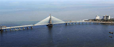
A triumph of precision engineering
Introduction
The Bandra-Worli Sea Link (BWSL) is a civil engineering marvel spanning an arc of the
Mumbai coastline. With its cable-stayed towers soaring gracefully skywards, the sea link is a
reflection of the modern infrastructure that Mumbai is adding in its progress towards
becoming a world-class city.
The BWSL project is a part of the Western Freeway Sea Project, which, in turn, is a part of a
larger proposal to upgrade the road transportation network of greater Mumbai. In the first
phase it will connect Bandra to Worli whereas in the subsequent phases the plans are to take
it further to Haji Ali and then to Nariman Point. It is a connecting bridge linking the city of
Mumbai with its western suburbs and has the potential to bring about permanent and far
reaching changes in the travel patterns of the area.
The Bandra-Worli Sea Link is primarily meant to provide an alternative to the Mahim
Causeway route that is presently the only connection between South Mumbai and the
Western and Central suburbs. The project starts from the interchange at Mahim intersection,
i.e. intersection of Western Express Highway and Swami Vivekanand Road at the Bandra
end, and connects it to Khan Abdul Gaffar Khan Road at the Worli end. The project has been
commissioned to offer a quicker alternative to the north-south traffic that presently amounts
to approximately 125,000 cars a day.
The project has been commissioned by the Maharashtra State Road Development
Corporation Ltd (MSRDC) and the Maharashtra Government and is being built by HCC
(Hindustan Construction Company). As a builder of landmark infrastructure projects around
the country, HCC has handled numerous challenges both in terms of location and technology.
The BWSL project offered HCC an opportunity to accomplish one more feat: to construct an
eight-lane freeway over the open sea for the first time in India.
Highlights in brief
• India’s first bridge to be constructed in open-sea conditions
• 4.7 km, twin, 4-lane independent carriageway bridge across the open sea
• 16-lane toll plaza with 20-m wide promenade together with state-of-the-art traffic
monitoring, surveillance, information and control systems
• 2342 pre-cast segments for total bridge with varied width
• 40,000 MT of reinforcement, 23,0000 cum of concrete, 5,400 MT of Post tensioning
strands and bars used
• Osterberg cell technology used for the first time in India to check pile strength (for up to
9600 MT).
• Engagement of Asian Hercules, one of the largest floating shear leg crane in the world for
shifting 1,260 MT launching truss from Bandra end to Worli end of the main cable stay
bridge
• Largest span for cable-stayed bridge in India
• Up to 25-m high pier in open sea, giving ample headroom to marine traffic
• Use of Polytron Disc in bearings on piers for the first time in India
Project overview
The entire project was originally conceived as one large project comprising, different
components, but in order to accelerate the overall construction schedule, the project has been
divided into five construction packages :-
Package I: Construction of flyover over Love Grove junction at Worli
Package II: Construction of cloverleaf interchange at Mahim intersection
Package III: Construction of solid approach road from the Mahim intersection up to the
start of the Toll Plaza on the Bandra side and a public promenade
Package IV: Construction of Cable-Stayed Bridges together with viaduct approaches
extending from Worli up to the Toll Plaza at Bandra end, Intelligent Bridge
System (IBS).
Package V: Improvement to Khan Abdul Gaffar Khan Road
Package IV is the largest and main phase of Bandra-Worli Sea Link Project.
Main features of
this technically challenging package are:
• Cable-Stayed Bridge including viaduct approaches extending from Worli up to Toll
Plaza at Bandra end
• Modern Toll Plaza
The work under this package was awarded to HCC.
Details of Package - IV
Main Bridge structure
The bridge consists of twin continuous concrete box girder bridge sections for traffic in each
direction. Each bridge section, except at the cable-stayed portion, is supported on piers
typically spaced at 50 meters. Each section is meant for four lanes of traffic, complete with
concrete barriers and service side-walks on one side. The bridge alignment is defined with
vertical and horizontal curves. The bridge layout is categorized into three different parts:
• Part 1 - The north-end approach structure with Pre-Cast (PC) segmental construction.
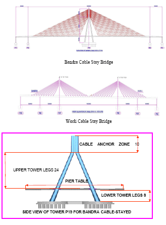
• Part 2 - The Cable-Stayed Bridge at Bandra channel is with 50m -250m-250m-50m
span arrangement and the Cable-Stayed Bridge at Worli channel is with 50m-50m-
150m-50m-50m span arrangement.
• Part 3 - The south end approach structure with Pre-Cast segmental construction.
Part - I North End approach structure
The bridge is arranged in units of typically six continuous spans of 50 meters each.
Expansion joints are provided at each end of the units. The superstructure and substructure
are designed in accordance with IRC codes. Specifications conform to the IRC standard with
supplementary specifications covering special items. The foundation consists of 1.5 meters
diameter drilled piles (4 nos. for each pier) with pile caps. Bridge bearings are of Disc Type.
The bridge has been built utilising the concept of Pre-Cast, post-tensioned, segmental
concrete box girder sections. An overhead gantry crane with self-launching capability is
custom built by the company to lay the superstructure of the precast segments. The Pre-Cast
segments are joined together using high strength epoxy glue with nominal prestressing
initially. The end segments adjacent to the pier are short segments "cast-in-situ joints".
Geometrical adjustments of the span are made before primary continuous tendons are
stressed.
Segment types are further defined by the changes in the web thickness and type of
diaphragms cast in cell. The segment weights vary from 110 tons to 140 tons per segment.
The segment length varies from 3000 mm to 3200 mm. Deck post tensioning is performed at
the completion of the erection of each 50m bridge span.
Part- II Cable-Stayed Bridge
The cable-stayed portion of the Bandra channel is 600 meters in overall length between
expansion joints and consists of two 250-meter cable supported main spans flanked by 50
meters conventional approach spans. A centre tower, with an overall height of 128 meters
above pile cap level, supports the superstructure by means of four planes of cable stay in a
semi-harp arrangement. Cable spacing is 6.0 meters along the bridge deck.
The cable-stayed portion of the Worli channel is 350 meters in overall length between
expansion joints and consists of one 150 meters cable supported main span flanked by two 50
meters conventional approach spans. A centre tower, with an overall height of 55 meters,
supports the superstructure above the pile cap level by means of four planes of cable stay in a
semi-harp arrangement. Cable spacing here is also 6.0 meters along the bridge deck.
The superstructure comprises twin precast concrete box girders with a fish belly cross
sectional shape, identical to the approaches. A typical Pre-Cast segment length is 3.0 meters
with the heaviest superstructure segment approaching 140 tons. Balanced cantilever
construction is used for erecting the cable supported superstructure as compared to span-byspan
construction for the approaches. For every second segment, cable anchorages are
provided.
A total of 264 cable stays are used at Bandra channel with cable lengths varying from
approximately 85 meters minimum to nearly 250 meters maximum. The tower is cast in-situ
reinforced concrete using the climbing form method of construction. The overall tower
configuration is an inverted "Y" shape with the inclined legs oriented along the axis of the
bridge. Tower cable anchorage recesses are achieved by use of formed pockets and transverse
and longitudinal bar post-tensioning is provided in the tower head to resist local cable forces.
A total of 160 cable stays are used at Worli channel with cable lengths varying from
approximately 30 meters minimum to nearly 80 meters maximum. Like the Bandra channel,
the tower here is also cast in-situ reinforced concrete using the climbing form method of
construction but the overall tower configuration is "I" shape with the inclined legs. Similarly,
tower cable anchorage recesses are achieved by use of formed pockets.
The foundations for the main tower comprise 2 meter-drilled shafts of 25 meters length each.
Cofferdam and tremie seal construction have been used to construct the six-meter deep
foundation in the dry.
Part - III South End approach structure
This portion of the bridge is similar to the North end approach structure in construction
methodology with span by span match cast concrete box girder sections.
Toll Plaza
A modern toll plaza with 16 lanes is provided at the Bandra end. The toll plaza is equipped
with a state-of-the-art toll collection system. A structure is provided at this location to house
the control system for the ITS.
Intelligent Bridge System
The toll station (TP) and collection system will provide for three different types of toll
collection, as follows:
- Fully automatic system: Electronic payment through On board Units mounted on the
vehicles which allow passage without stopping.
- Semi-automatic system: Electronic payment through a smart card, which allows
payment without having to pay cash.
- Manual toll collection: Payment of toll by cash, requiring vehicle drivers to make
cash payment to a toll attendant, and stopping for cash exchange.
The intelligent bridge system will provide additional traffic information, surveillance,
monitoring and control systems. It comprises CCTVs, traffic counting and vehicle
classification system, variable message signs, remote weather information system and
emergency telephones. The control centre located near the toll plaza is housed with the
electronic tolling controls. The transmission system comprises fiber-optic cable housed in
PVC conduits running parallel to the Bandra-Worli corridor. In addition, facilities to assist
enforcement are provided in the form of pullout locations, which will allow drivers and
enforcement officers to safely pullout of traffic.
Power Supply Distribution and Road Lighting System
A reliable and dependable power supply has been arranged for the entire project. It will also
house diesel generator sets and auto mains failure panels to cater to critical load, e.g.,
monitoring, surveillance and communication equipment emergency services like aviation
obstruction lights. Adequate levels of lighting levels have been maintained and energy saving
luminaries have been installed. Special emphasis has been given to incorporate lighting
protection at bridge tower and control room building to protect those building/ structures and
the sophisticated monitoring and communication equipment installed therein.
Challenges encountered during execution of the project
Engineering challenges
BWSL Project is a unique and pleasing structure, but before undertaking the construction,
following were the major challenges to be addressed:-
• The foundations of the bridge included 604 large diameter shafts drilled to lengths of 6m
to 34m in geotechnical conditions that varied from highly weathered volcanic material to
massive high strength rocks.
• The superstructure of the approach bridges were the heaviest spans in the country to be
built with span-by-span method using overhead gantry through a series of vertical and
horizontal curves.
• A one-of-its-kind, diamond shaped 128m high concrete tower with flaring lower legs,
converging upper legs, unified tower head housing the stays and a throughout varying
cross section along the height of tower.
• Erection of 20000 MT Bandra cable-stayed deck supported on stay cables within a very
close tolerance of deviations in plan and elevation.
The challenges were varied and started right from the Pre-Cast yard.
Ground stabilisation for Pre-Cast Yard
The Pre-Cast yard is located on reclaimed land. The yard caters to casting, storing and
handling of pre-cast segments for the project totaling 2342 in numbers. The storage capacity
requirement of yard is to be about 470nos. As the area available is limited, the segments are
to be stored in stacks of three layers.
The bearing capacity of the ground is of paramount importance to enable three-tier storage of
segments. As the pre-cast area is on reclaimed land, the bearing capacity of existing ground
was very poor and found to be less than 2 T/Sqm.
Hence detailed ground stabilization was carried out, which involved following:
• Excavation of the ground to a depth of ~ 2.5Mtrs.
• Strengthening the ground using rubble soling and filling the voids with sand. The soling
thus done was compacted layer by layer using vibratory rollers.
• Total area of the Pre-cast Yard was covered with a layer of PCC.
• RCC Footing done to facilitate storing of segments.
These measures offered the required strength to the casting yard.
Marine works
Foundation and substructure
The foundations for the BWSL project consist of 2000-mm diameter piles numbering 120 for
the cable-stayed bridges and 1500-mm diameter piles numbering 484 for the approach
bridges. The project’s site geology consists of basalts, volcanic tuffs and breccias with some
intertrappean deposits. These are overlain by completely weathered rocks and residual soil.
The strength of these rocks range from extremely weak to extremely strong and their
conditions range from highly weathered and fractured, to fresh, massive and intact. The
weathered rock beds are further overlain by transported soil, calcareous sandstone and thin
bed of coarse grained conglomerate. The top of these strata are overlain by marine soil layer
up to 9m thick consisting of dark brown clayey silt with some fine sand overlying weathered,
dark brown basaltic boulders embedded in the silt. The major engineering problems that
needed suitable solutions before proceeding with the work were as follows:
1. Highly variable geotechnical conditions of the foundation bed as explained above.
2. Highly uneven foundation bed even for plan area of one pile.
3. Presence of Intertidal Zone (Foundation Bed exposed in low tide and submerged in high
tide).
The key to success was a program of pier by pier in-situ testing. An extensive subsurface
exploration and drilling program (total 191 bores inside sea) was undertaken to define the
subsurface stratigraphy, determine the rock types and obtain material properties for
optimizing the foundation design. Owing to a highly
variable geology, the design calculations were
performed on a pier-by-pier basis and the unit side
shear values were checked that they did not exceed
the load test results under similar rock conditions.
The working load on the approach piles ranges from
700 tons to 1500 tons whereas for the piles below
the cable-stayed bridge working load is 2500 tons.
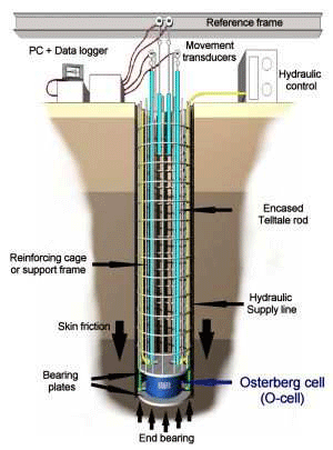
For conducting the load test on the piles, the load to
be applied varied from 4500tons to 9600tons.
Arranging reactions for such loads either by normal
kentledge method or by soil anchor required massive
scale arrangements in the sea waters. This was
completely avoided by a careful planning of load
test using the Osterberg load cell method (Refer
sketch 1).
The award winning Osterberg Cell, or "O-Cell', gets its name from the inventor, Dr. Jorj O.
Osterberg. The O-cell is a hydraulically driven, high capacity, sacrificial loading device
installed within the foundation unit. Working in two directions, upward against side-shear
and downward against end-bearing, the O-cell automatically separates the resistance
parameters. By virtue of its installation within the foundation member, the Osterberg Cell
load test is not restricted by overhead structural beams and tie-down piles. Instead, the O-Cell
derives all reaction from the soil and/or rock system. End bearing provides reaction for the
skin friction portion of the O-Cell load test, and skin friction provides reaction for the end
bearing portion of the test. Load testing with the O-Cell continues until one of three things
occurs: ultimate skin friction capacity is reached, ultimate end bearing capacity is reached, or
the maximum O-cell capacity is reached.
Each Osterberg Cell is specially instrumented to allow for direct measurement of the end
bearing and skin friction. O-Cells range in capacities from 0.7 MN to 27 MN. By using
multiple O-Cells on a single horizontal plane, the available test capacity can be increased to
more than 200 MN. At BWSL, four test locations were selected for the following criterion.
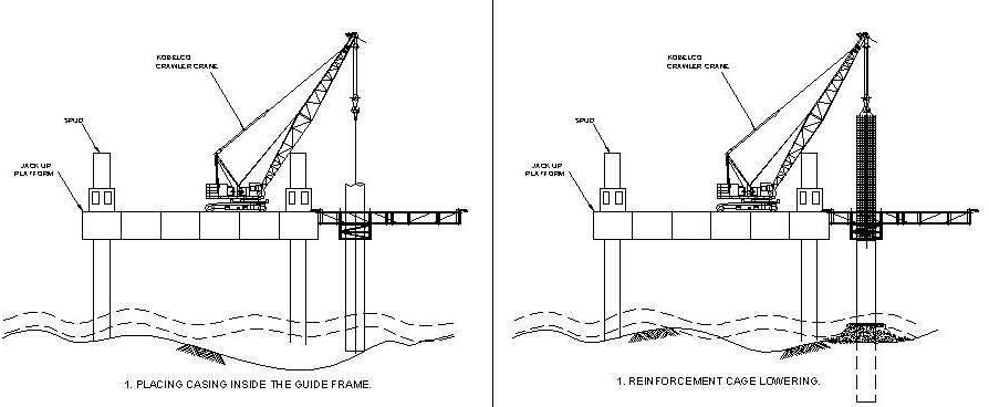
Reverse Circulation Drilling method is adopted for foundation construction. The highly
uneven foundation beds and the presence of intertidal zone brought in lots of difficulty in
terms of Liner pitching. This problem was solved by constructing a gabion boundary at the
bed level around the casing, pouring concrete between the casings to make an artificial
penetration of the casing. After setting of the concrete under the water, drilling was
commenced using RCD.
It is interesting also to mention that loss of water head during continuous drilling operation
was a major problem while working in the intertidal zone. This water head loss leads to very
slow production rate and very high consumption of drill bits. To overcome this problem, pits
were made in the low tide at each foundation location using an Excavator and the casing was
placed at the bottom of the pits. Then the casing was placed in the pits and was concreted to
make an artificial penetration, maintaining the proper water head for continuous drilling.
For several locations, cofferdam
construction using steel liner and sheet
piles, was not possible due to very hard
and uneven strata. Here the problem was
solved using circular steel caissons. These
caissons were fabricated outside and towed
to location using A-frame barge. The
caissons were sunk at the location using
counterweights. The unevenness at the bottom was sealed using the gabion method. The
benefit of this method was that it completely eliminated deployment of resources like Jack up
Platform, Crane, Vibrohammer, Compressor, etc for liner pitching. It also eliminated
substantial amount of field works and is pre-fabricated in principle.

Superstructure
The BWSL Project has (9+2) approach bridge modules. These modules range from 3
continuous span units to 8 continuous span units. The deck of the carriageways consists of
triple cell precast box girders supported on piers founded on independent substructure. The
Concrete Grade for the superstructure is M60. The average weight of the span is 1800 tons,
whereas the heaviest span in the bridge (to be erected with the Launching Gantry) weighs
2000 tons. In addition, the trusses were to be designed to receive the segment from the
already erected deck as well as from barges parked directly under the truss.
The Technical Data for the superstructure is as follows.
Max Longitudinal Gradient = 1.72%
Max Crossfall = 6%
Max Radius in Plan = 600m
Min Radius in Plan = 246m
Typical Span Length = 50m and 30m in Link Bridge
Max Span Weight = 2000 tons
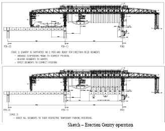
The erection gantry is 1260MT truss designed to erect spans for the above configuration. The
unique feature of the truss indeed is the maximum span weight it can handle and that it can
launch the pier and EJ segment itself. The truss also has the capacity to align the total span in
hanging condition after the gluing is completed. The truss is fully mechanized for self
launching and aligning. An individual segment can be aligned on the truss using a set of four
hydraulic jacks mounted on each suspension frame. In order to eliminate the casting or
erection errors within a span, two wet joints are provided on either end of the span. The wet
joints are cast after finalization of the span alignment.
For the fabrication of the truss, the entire structural steel (grade Fe 540) was sourced from
within India. The accessories and components however were procured from India and abroad.
A full scale load test was conducted before putting the erection gantry into actual operation.
The erection gantry comprises the following:
a. Main truss
b. Front/rear pylons
c. Front/centre/rear legs
d. Front /rear trolley
e. Cross beams
f. Stressing gondola
g. Suspension frames
h. Connection beams-Type A/B
i. Spreader beams- Type A/B
j. Pier bracket
k. Chain Support
A Typical 50m span of the approach bridges comprises 15 field segments, a Pier segment and
200mm (nominal) in-situ wet joints. During the span construction, all field segments are
suspended from the Gantry, glued and temporarily stressed together. Once the gluing
operation is completed, span alignment to the Piers is followed. After alignment, the wet
joints are cast including grouting of bearings top plinth. Once the wet joints achieve the
required strength, stressing of longitudinal PT is commenced followed by load transfer of
Span to Piers.
Relocation of Launching Trusses using 1600MT capacity Barge Mounted Crane - Asian
Hercules
After the successful erection of the deck on Bandra side, the trusses were required to be
shifted across the Bandra cable stay bridge by 600 meters to Worli side to take up the spans
beyond the Bandra Cable Stay.
Various options like (i) dismantling of the trusses at present locations and reassembling them
at new locations, (ii) lowering the trusses on a suitable floating craft and shifting and erecting
them, and (iii) shifting the total truss using a floating crane, etc were analyzed in detail.
Taking into consideration various constraints like limited working period available to execute
the work in sea, the effect of open sea on dismantling and re-erection, etc, the best option
available was the relocation of the trusses in one piece using a floating crane.
Asian Hercules is one of the biggest floating shear leg cranes in the world. This crane is
mounted on a barge which is over 240 feet long and more than 130 feet wide, weighs 5,900
tons and has enough lifting capacity (1600 MT) to lift a weight equal to 2,000 small cars. It
started its voyage from Singapore on October 9, 2006, and arrived at Mumbai's shores on
October 27, 2006. After obtaining the necessary regulatory clearances, it commenced
operations from November 06, 2006, including trial runs and realignments in its settings.
Selection of equipment was done considering various challenges, like the draft and space
available at working locations, tide limitations, and other weather constraints.
The process: The biggest hurdle on the Asian Hercules operation was that the draft at the
required locations was not good enough to carry out the operation smoothly without
disturbing the VSNL cable lying underneath. This problem was overcome by using
sophisticated global positioning system and carrying out the entire operation in a series of
smaller operations during the favourable high-tide. First the Asian Hercules Crane was
positioned at the required lifting position. A complex operation of balancing the vessel using
ballasting was carried out as per the predetermined stages. Positioning of the vessel was done
considering the draft requirements. A specially fabricated lifting spreader was fixed to the
truss to facilitate the lifting.
The truss load was taken by the crane in stages so that the lifting operation was smooth.
Through computerized central monitoring, the load in individual lifting points was monitored
to ensure that no point was overloaded.
After taking the load, the Asian Hercules crane was moved to a safe location where enough
water depth (draft) was available to park the crane with the truss. Then the crane with the
truss was moved to a new location during the next high tide. The truss was then lowered on to
the final location. The lowering of truss at the final location was achieved through Guides,
which helped to achieve a final placement accuracy of ±50mm. The operation, which
otherwise would have taken one complete year, was completed in matters of a few days.
Cable Stay bridges
It is for the first time that cable stay bridges have been attempted on open seas in India.
Coupled with the fact that the aesthetically designed pylons have an extremely complex
geometry and one of the longest spans for concrete deck, the challenges encountered were
indeed formidable.
Construction of Pylon Tower Legs
The salient characteristics of the pylon tower that make it complex and challenging from the
point of view of constructability are as follows:
(a) The section decreases gradually with height;
(b) There are horizontal grooves at every 3m height and vertical grooves for circular
portion that requires special form liners as well as it requires attention for deshuttering;
PIER TABLE
CABLE ANCHOR ZONE 10
LIFTS
UPPER TOWER LEGS 24
LIFTS
LOWER TOWER LEGS 8
LIFTS
SIDE VIEW OF TOWER P19 FOR BANDRA CABLE-STAYED
BRIDGE
(c) The tower legs are inclined in two directions, which creates complexities in
alignment and climbing of soldiers;
(d) Construction joints permitted only at 3m level. Inserts were permitted only in
horizontal grooves provided at 3m height.
On not being able to get immediate solution from reputed worldwide formwork
manufacturers, the project design team designed an automatic climbing shutter formwork
system, which was fabricated on site and employed to execute all tower leg lifts below deck
level. To affect further reduction in time cycles, HCC approached Doka, Austria. Doka
then devised a customized solution based on their SKE-100 automatic climbing shutter
system.
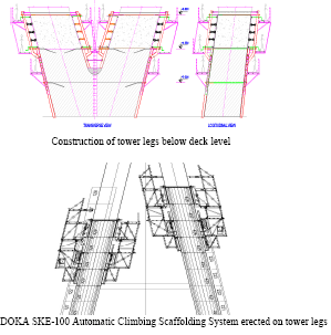
Construction of tower legs below deck level
DOKA SKE-100 Automatic Climbing Scaffolding System erected on tower legs
a. Survey of Tower Legs
The complex pylon geometry was another challenge for surveyors. Coupled with geometry,
the construction stage analysis indicated leaning and progressively increasing inward
inclination of pylon legs during construction. HCC’s Principal Surveyor devised a
sophisticated technology to measure coordinates through a combination of total station and
prisms mounted on pylon legs. The temperature and construction stage analysis factors
were applied to derive the corrected coordinates. The pylon legs were constructed within an
accuracy of ±5mm, which speaks volumes about the technique employed.]
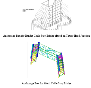
b. Anchorage Box
Anchorage Box for Bandra Cable Stay Bridge placed on Tower Head Junction
Anchorage Box for Worli Cable Stay Bridge
Anchorage Box is used as inner shuttering for tower head. Bearing plates with guide pipes are
fixed to the anchorage box. Guide Pipe and Bearing Plates actually transfer the deck loads to
tower concrete which are generated due to stressing of stay cables. The anchorage box is
fabricated with 12mm thick high grade steel plates. It is fabricated in pieces and then bolted
at tower head portion. The bearing plates and guide pipes of anchorage box are galvanized
and the remaining portion was painted with anticorrosive polyurethane based paint.
Anchorage boxes are fixed with the help of co-ordinate system for accurately fixing the
anchorage point and angle of stay cable.
c. Compression struts
Compression struts are provided at various levels of tower legs. These were basically
provided to keep the alignment of all tower legs in their required position. During
construction, due to geometry it was possible that the tower legs might lean inwards due to
weight and stresses involved in the base. In order to avoid that, compression struts were
provided and jacking done to desired load to maintain the alignment.
d. Erection of Pier Table segments
The pier table segments numbering 42 for both the carriageways were another hurdle
encountered. The reasons being –
(a) Launching Truss could not be deployed;
(b) Being generally over the pylon pile cap, lifting segments from the sea was not
possible. To overcome this hurdle, HCC’s Expat devised a brilliant and ingenious
solution in the form of –
-Pier Table Trusses (PTT): One each was erected for each carriageway. It
had rails on top to move segments with the help of hydraulic jacks from one end
to another.
-Lifting Frame: This was an ingenious little devise mounted at either end of PTT.
SLU (Strand Lifting Units) were mounted on top to lift the segment from barges
anchored in the sea. After lifting the segment, the front frame closed down,
where the segment was lowered on the rails. The rear frame lifted up to enable
the segment to slide across the PTT hydraulically.
STAGE: 1
Open the Support Bracket
and Lift the Segment.
Close the Support
Bracket, Slide in the
Trolley and Lower the
Segment on Sliding
Trolley
STAGE: 2
Opening of the Lifting Boom & Strut, Slide out the Segment and Close the Lifting Boom and & Strut. Repeat operations for the other segment lifting.
e. Erection of segments of Cable Stay Bridge by Derrick
The method used for erection of segments at Cable-Stayed bridge was balance cantilever
construction method. During construction, the length of free cantilever for Bandra Cable-
Stayed bridge was 215m and for Worli Cable-Stayed bridge it was 73m.
The segments were lifted by the instrument named Derrick which was fixed on both ends of
the pier table segment and then forwarded. Lifting operation was done simultaneously on
both ends. At a time, Derrick can lift one segment. Deck is constructed of alternate stay and
non stay segments joined to
pier table segments.
Lifting of Segment with Derrick
f. Dry Matching, Epoxy and temporary stressing for gluing
When the segment is positioned, it is to be joined with the existing segment. Therefore, the
segment was first dry-matched with the already erected segment. On completion of drymatching,
the segment was moved back by sliding the lifting beam for a distance of 400mm
of the derrick and epoxy was applied on the face of both segments. After application of the
glue, the segments were joined together and were stressed by Temporary PT bars. Post this
step, the segment lifting beam on derrick is moved forward to lift the next segment i.e. stay
segment.
g. Erection of Stay segment
These segments were also erected similarly as the non-stay segment and were also joined in
the similar way. After this, guide pipes were installed over the ducts left behind during
segment casting.
h. Stay cable
Stay Cables used are ‘Parallel Wire Stay Cables’. They were manufactured by “Shanghai
Pujiang Cable Co. Ltd” China. Each cable consists of a group of different number of steel
wires. Each wire is made up of high tensile steel. Diameter of single wire was 7mm with a
breaking limit of 6.28 Tones. Six different sizes of cables were used in the cable-stayed
portion. The difference between them was only on the basis of number of steel wires in each
cable. Six different types used were of 61, 73, 85, 91, 109 and 121 steel wires. Group of these
wires was packed in two layers of HDPE (High Density Poly Ethylene) material to protect
them from atmospheric effects.
Typical Cross Section of Stay Cable
i. Closure pour
In Bandra Cable-Stayed Bridge, closure pour is provided between main cable-stayed
cantilevers and back span. In Worli Cable-Stayed bridge, closure pour is provided between
two cable-stayed cantilever decks
j. Longitudinal stressing and grouting
When all the segments and cables were erected, the segments were post tensioned
longitudinally. This post tensioning was done by stressing the steel tendons placed in the
ducts provided inside the body of segments. This helps the members to stay together and to
increase their load carrying capacity as a large number of segments were joined together to
make single unit. Once the stressing was done as per requirement, these holes or ducts were
filled with cement grout and were plugged at both ends.
k. Fine tuning
After completion of closure pour and post-tensioning of the deck, fine tuning of stay cables is
done. Fine tuning is fine force adjustments of the stay cables to achieve the required stresses
in the deck and profile of the deck.
During fine tuning, forces in the stay cables are adjusted to suit further addition of superimposed
dead loads such as wearing coat, crash barriers, handrails and also vehicle loads.
During fine tuning operation, longitudinal and transverse deck profiles are also monitored to
provide smooth curve.
l. Wearing Coat over south bound bridge deck
Bridge deck surface of south bound carriageway is provided with 40mm thick Polymer
Modified Bituminous pavement in conjunction with water-proofing system to seal the bridge
deck.
Working during monsoon
The Maritime Board does not allow marine traffic in monsoon season. Thus, work was halted
mid-May only to re-commence in October, effectively reducing the work schedule to only
seven months in a year. To overcome this hurdle and to use this time to speed up the
construction activities at Bandra Pylon, HCC put forth the solution in the form of an
innovatively designed temporary bridge. This bridge had a total length of 325 metres. It had
the facility of a walkway, a concrete pipe line, an electrically-operated trolley mounted on
rail, water line and a pipe line. It paved the way for successful continuation of work during
the monsoon season when the sea was rough and the winds were strong.
Logistics
Another challenge was ensuring effective supply chain at all working locations spread across
the alignment in the sea and formulating measures to ensure the same. A diligently worked
out logistic plan was put into action to ensure that commodities were handled at dedicated
location and dispatches monitored meticulously. State-of-the-art electronic devices were
placed on the barges to cut down on idle timings.
During peak construction activities, innovative procedures and specialized equipments were
required to enable high accuracy. Expert crews had to also exercise good judgement in
assessing sea behavior and priorities during foundation/ substructure constructions and final
placement of concrete in situ. Navigation and transporting 19 precast segments in 24 hours at
different open sea locations was a challenge. Secondly, concrete consumption at the peak had
been at the rate of 50cum/hr. Under marine conditions, the consumption rate has been in the
order of 700cum per day. To add to this, maintaining adequate food supply for around 2500
people (in a shift) working in the sea at over 30 locations was a big challenge. These
complete requirements were met with an effective utilization of a fleet of 30 marine vessels
including 13 barges for concrete, segments and material transport, eight steel boats for
material and workers transport, three tug boats and six smaller passenger boats.
Around four passenger boats were used for carrying food to approximately 30 locations in the
sea. Each employee, while starting his day, entered the log indicating the location at which
they would be working. Thereafter began the clockwork of gathering tiffin boxes, washing
and cleaning, allocation and dispatch as per the log entries along with the drinking water
supply including tea supply at two time intervals per shift. During rough sea conditions in
the normal working season, extra tiffins were carried to take care of possible spillage while
transferring the tiffins from boats to working locations. Thus workers were also suitably
cared for, while meeting the engineering challenges posed during construction of the Bandra-
Worli Sea Link.
Psychological conditioning
With a long track record and experienced in building large infrastructure projects, HCC
follows strict guidelines for occupational health and safety and environment protection.
Safety is extremely important to HCC and the company officials worked towards sensitising
labour and creating greater awareness of safety standards with gentle persuasion, consistent
motivation and tool box meetings. The kind of structured processes that were implemented by
HCC for ensuring safety is nothing short of phenomenal.
Lack of awareness is the biggest hazard for safety. Since the primary safety hazard are related
to engineering control, equipment, job methodology, material handling, structural fabrication
and emergency preparedness, HCC made sure that every worker is taken through the HSE
program. The orientation program made them aware of the various safety hazards associated
with a project and necessary precautions to be taken to prevent them. They are also taught
how to evacuate during any emergency. For its meticulous planning and implementation of
safety practices for the BWSL project, HCC has won the prestigious “Golden Peacock
Award” for safety, health and environment in June 2007.
Key people
Over 3000 workers were employed to work on the project. Several teams of HCC engineers
and foreign engineers and technicians have been involved in specialised tasks on the structure
of the Sea Link. These include professionals from China, Egypt, Canada, Switzerland,
Britain, Serbia, Australia, Singapore, Thailand, Hong Kong, Indonesia and the Philippines. In
terms of language, cultural differences and methods of work these key people were different,
yet the engineering challenges kept the group creatively involved, and they worked
enthusiastically as a team.
“This project gave us an opportunity to
showcase our equipment”
 Rakesh Kaul Rakesh Kaul
says Rakesh Kaul,
General Manager, Elcome
Technologies Pvt. Ltd.,
with reference to the
survey equipment that
they supplied for the
Bandra-Worli Sea Link.
|
When did Elcome Technologies first
get associated with HCC on the
Bandra- Worli Sea Link Project?
Leica equipment has been used
on most of the Sea Link projects
around the world and based on this
experience we approached Hindustan
Construction Company (HCC)
sometime at the end of 2000 with our
range of specialised equipments for
the Bandra-Worli Sea Link (BWSL).
The first Leica Total Station was
supplied by us to HCC in early 2001.
What were the equipment
supplied for this project?
To meet the demand for high accuracy
coordinate measurements on the BWSL
project we supplied high performance
Leica Total Stations including the TCA
2003, the TCA 1800, the TCA 1201, the
TCRM 1201 R 300 and the TC 1800. We
also supplied the SR 510 GPS equipment.
What kind of support did you
provide HCC vis-à-vis the equipment
that you supplied to them?
We gave comprehensive application
trainings at their site towards effective
and optimal usage of the equipment.
Moreover, these equipments in keeping
the desired accuracies that are required
for such a project, needed timely
calibration checks and corrections – for
this, besides providing them complete
service support during the warranty,
we also got into annual maintenance
contracts for these equipment post their
warranty period. We were thus able to
provide timely service and calibration
of the equipment at our service centre.
Do you think being associated with the
project gives Elcome Technologies any
leverage for other similar projects?
It has been a privilege to be associated
with BWSL and the HCC team we
worked with. Moreover the challenges
in geometric control on the project were
highly demanding and exacting. This
gave us an opportunity to showcase
our equipment and our expertise.
Our experience with BWSL project
will be a basis for us to promote our
technology on other such projects too.
|
|