| Navigation | |
Safe Navigation for autonomous Robot systems
The project SiNafaR (German acronym for “Sichere Navigation für autonome Robotikplattformen”) aims for identifying requirements, legal aspects in Germany, and finding technological solutions for heterogeneous multiagent systems in the civilian sector, especially in the domain of security services covering large areas |
 |
|
 |
|
 |
|
 |
|
 |
|
 |
|
The project SiNafaR concentrates on surveilling big areas like container harbors with autonomous and heterogonous robots supporting the security staff. A combined network of heterogeneous agents takes advantage of the different capabilities to solve complex problems like surveillance. On the one hand, the high maximum velocity of an UAVs and the absence of obstacles in greater heights allow a fast approach of a single point. UGVs, on the other hand, offer a higher operation time, and therefore allow constant patrolling. But they can only provide video stream of a frog-perspective und suffer from connection loss due to ground structures. Therefore a combination of both advantages is beneficial.
Despite the system concept of a heterogeneous surveillance system, its information and data flow, special attention is drawn to the precise and reliable positioning, by means of local and global navigation. For setting up such a system in the civil domain, precise determination of the location of each node is essential. In order to avoid accidents with persons or collision with infrastructure elements, a robot device must have knowledge about its own position and the surrounding environment. A commonly used position determination system for outdoor applications is Global Navigation Satellite System (GNSS) with the currently available systems Global Positioning System (GPS) and GLONASS. GNSS systems suffer from unpredictable errors caused by atmospheric noise, satellite failures or multipath effects, which could lead to invalid position information. For the project SiNafaR, a new system has been developed to detect noise, multipath conditions or faulty GPS-data. Fraunhofer IIS has developed a GPS receiver solution based on real-timekinematic (RTK), enabling a conservative quality evaluation of the current localization data. Using a base station and more than one low-cost GPS receiver on the robots, the system can judge whether the data is valid or degraded by undesired effects. The solution includes a consideration of noise within the GPS pseudoranges as well as a special channel detecting multipath effects, and the fault detection and identification (FDI) algorithm FIBSI [10] developed by Fraunhofer IIS. In case of unreliable position information, the robot can switch to fallback solutions instead of using the potentially wrong GPS data.
Moving autonomously from A to B requires several technical capabilities such as automatic control, path tracking, and collision avoidance. Those tasks have been solved by the robot MERLIN developed by the University of Wuerzburg. Besides the GPS localization information, navigation can be supported by several additional ambiance sensors. For the movement of the robots themselves, certain restrictions such as the Ackermann steering model, environmental constraints (e.g. moving obstacles) etc. must be taken into account.
Another mission-critical part of this project is a stable and high-performance radio-link between the entities. Therefore, the communications research department of EADS Innovation Works has developed a wireless communication system fulfilling these requirements based on Orthogonal Frequency Domain Multiplexing (OFDM) channels. The data is split in two categories, commands and video streams. The commands need low bandwidth but high reliability. The video streams need much more bandwidth, but a few lost packets might be acceptable. To benefit from this factor, these two streams are modulated with different degrees of robustness against disturbance.
On top of this physical layer, a generic network-based data infrastructure which synchronizes the data among all components has been developed by the ZfT. The infrastructure consists of the base station, which is the main server handling all data, and a library package, which contains the client and commonly used functionalities. To ease the development, this package can be imported in every Java or even Android project enabling them access to the data. The infrastructure is liable to synchronize the data of all components without any manual intervention of other program parts, and to inform the other program parts of changes like changed robot positions and emerged events. The communication is based on the TCP/ IP protocol, so the components can be distributed world-wide. The messages are packaged using JavaScript Object Notation (JSON), a human-readable data format to ease the development and debugging while keeping them compact (compared to XML).
Furthermore, ZfT has developed a browser based human-machine interface following the expert knowledge of a professional surveillance provider from Wilkon e.K. to demonstrate the suitability of the GUI even for users who are not professionally trained in robot systems. This system considers heterogeneous agents to profit from the special advantages of each robot type. Additionally, a scheduler was created to allow automated tasks, which are time-driven, and interventions, which are eventdriven.
For testing scenarios, navigation algorithms and especially video camera positions, a simulation framework was build based on USARSim [12], which can be easily integrated in the graphical user interface (GUI) to augment real video information. Using this simulation as source for sensor data and as sink for control inputs of the used middleware Robot Operating System (ROS) a transparent transition between simulation, hardware-in-theloop (HIL) simulations and operation with real hardware, based on the same ROS-modules is possible.
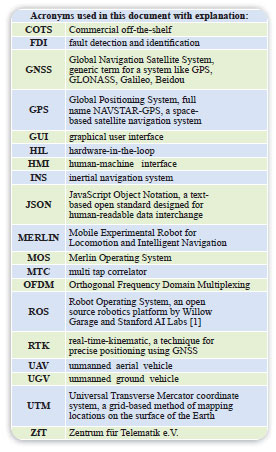
Besides developing a demonstrator study for the surveillance scenario described above consisting of an unmanned helicopter and an unmanned ground vehicle, the project has achieved many results, which can be used for future projects in different kinds of application areas (also see Figure 1).
UAV/UGV Platform
UAV Platform
For the UAV demonstrator platform a fuel powered helicopter was selected. It provides relatively easy maintenance and consists of inexpensive components but delivers a satisfying payload capability. Also, legal concerns are far easier compared to heavier UAV alternatives.
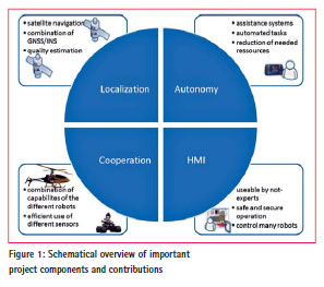
The UAV features a Commercial offthe- shelf (COTS) autopilot which is commanded by a list of waypoints. Figure 2 shows the hardware components in a schematic.
The live video was transferred using a 5 GHz WLAN connection delivering a MJPEG video stream to the ground station. The range of the WLAN was shown to be 100 m with simple antennas which was sufficient for the planned demonstration locations. Additionally the UAV features a pan-tilt-camera controllable by the user from the ground station, e.g. to search the vicinity of the UGV for obstacles. Using this, the navigation of the UGV can be further supported. Telecommand and position information are transmitted using separate data links.
The UAV has an onboard computer that handles route planning, marker detection and communication. Therefore the UAV has all necessary functionality onboard to follow the UGV autonomously.
UGV Platform
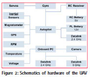
In order to meet the requirements made with respect to robustness, payload, and size, a small car-like robot was chosen as UGV demonstrator platform. The Mobile Experimental Robot for Locomotion and Intelligent Navigation (MERLIN) has been selected as foundation and was adapted and extended to fulfill the requirements. UGV Hardware (Figure 3): The MERLIN robot is a small car-like robot, developed since the early 90’s [8] and used in teaching and different different research projects. The chassis is built from highly durable offtheshelf components taken from the RC-Racing sector, accompanied by inhouse developed electronics and power systems, sensors and a powerful, yet energy efficient computer. For the proposed application, a laser range finder is used for obstacle detection and the built-in pantilt-zoom camera delivers the video stream important for the surveillance task. The builtin dead reckoning system, based on information of a gyroscope and an odometer, allows locomotion based on local information. A standard WIficonnection was used as data link for the further work.
UGV Software: The software of the MERLIN robots consists of two different parts, a real-time operating system and modules for the micro electronics as well as a standard operating system, a middle-ware and modules for the on board PC. The real-time operating system Merlin Operating System (MOS) is an in-house development, which implements the connection to the actuators and the on board sensors. The real-time capabilities enable the integration of short control loops and low-level drive assistance functions, as well as processing of the internal sensor data. [9]
The software responsible for highlevel tasks is based on the middleware ROS [1] in its version fuerte. For the aforementioned framework modules have been developed to allow connection between the main processing platform and the microelectronics of the UGV and therefore providing full control of the robot to the ROS layer. Footing on this middleware the development and integration of the necessary position controller, the obstacle avoidance, the positioning system and the connection to the application network could be easily handled in a distributed manner.
UGV Simulation: To simplify development the existing UGV was modeled in the simulation environment and integrated into ROS which allowed transparent switching between simulated components and real hardware in HIL simulation as well as in the complete live system.
Localization and navigation
Fraunhofer IIS mainly contributed to the following topics: Localization, methods for estimating the GNSS delivered positioning quality, the GNSS/inertial navigation system (INS) coupling, evaluation of sensors for distance control and collision avoidance.
GNSS localization
One goal was to develop a robust and precise solution for localization based on GNSS that conforms to the requirements of autonomous or partially autonomous mobile robotics. Thereby it is especially important to detect anomalous or faulty GNSS-signals and subsequently discard position solution output with inadequate accuracy.
Multiple possibilities to detect disturbances in the GNSS have been discussed:
• Signal-to-noise ratio (SNR) observations: The classical investigation, weighting and subsequent exclusion of individual GNSS signals based on measured or derived signal strength values and their comparison with appropriate expected values
• FDI: The detection and unambiguous identification of anomalies in individual GNSS signals as a base for exclusion of these signals from further processing multi tap correlator (MTC): A new approach for the detection and mitigation of multipath effects using high resolution in the correlation module of the digital signal processing parts of the GNSS receiver system
• A combination of the above mentioned methods in a novel system design to detect errors early and suppress or limit their impact on the position calculation
For this project a GPS-RTK solution with its own base station was selected. Therefore, many error sources in the GNSS can already be corrected by the use of a base station. Also for effects like multipath methods are presented to detect these at the rover location whereas the base station must be placed in a suitable location where no multipath is present.
Due to restrictions in the selection of the GNSS receiver for the UGV not all proposed methods could be realized on the complete system demonstrator. For the base station and rover the same low cost COTS receiver [2] was used. A proper antenna with low phase center variation proved to be essential on both sides. In this project the Fraunhofer IIS 3G+C antenna [7] was used. The receiver itself is not able to calculate RTK solutions, so the open source software RTKLIB [3] was integrated as a ROS node. The RTK base station was connected to the ground control station (see section IV) and correction measurements were sent via TCP to the rover.
The RTK ROS node contains a filter to exclude positions when a threshold for the confidence value of the over-determined equation systems of the RTK solution was exceeded. This approach allowed in virtually all cases a very convincing and a sufficiently accurate localization information regarding the absolute position of the UGV.
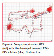
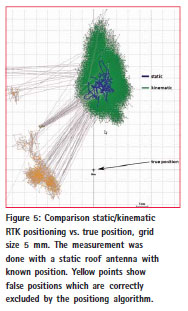
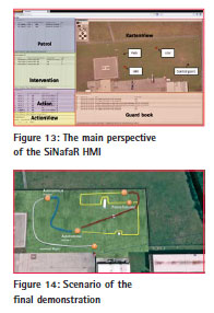
Figure 4 shows the route driven during the final demonstration event. The red line shows the result of the standalone, single frequency GPS algorithm, the blue line illustrates the result yielded by the developed RTK system. What can be seen is that the selected method generates positions with much higher precision. The movement of the UGV is easily discernible. Furthermore, periods with dark yellow color instead of blue indicate that the calculated position did not meet the safety margins. Figure 5 shows a computed solutions of static and kinematic RTK positioning in comparison to the known true position.
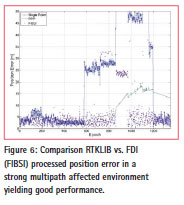
The mentioned FDI approach was implemented based on [10]. Figure 6 shows the performance in comparison to the standard RTKLIB positioning in a multipath effected environment. Using RTKLIB some errors can not be corrected. The FDI method FIBSI can detect these errors, identify the faulty sources and exclude them, yielding sufficient positioning performance even under strong multipath influence.
Sensors for distance control
In order to enable the UGV to fulfill the task of autonomous patrolling, a planned path, a position controller and an obstacle avoidance are necessary features. Based on the currently available sensors which are also used in present projects regarding robotics a set usable for obstacle detection should be found by conducting a multitude of tests according to the requirements which have been set for the project. Three current systems for detection of the local environment of a robot system have been compared: the CamCube 3.0 [4], the Microsoft Kinect [5] and a laser scanner by Hokuyo [6].
While the first two have the advantage of generating a 3D image which potentially includes higher detail, the laser scanner only measures the range in slices. Theoretically the 3D images would also allow to also detect negative obstacles, however these sensors mainly suffer from limited range, field of view, and problems in direct sunlight. Especially, the Kinect can be regarded as an indoor sensor for short ranges. Therefore, with respect to range and robustness in outdoor, the laser scanner is by far superior to the available 3D cameras.
GPS/odometry coupling
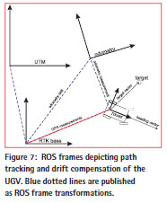
The navigation of the UGV uses local position information based on dead reckoning. This source suffers from errors caused by wheel slipping and the drift of the gyroscope. Hence, the proposed GNSS positioning solution is used as a global reference, correcting the drift of the local odometry system by use of this so called domain based localization approach, calculating the relation between the GPS frame and the local odometry frame. To get a robust and predictable behavior the data from GNSS and odometry were not combined in a filter (most robot systems use a Kalman filter), but presented in hierarchical coordinate systems (see Figure 7). The outermost system was the world coordinate frame fixed to the global geo coordinates expressed in the Universal Transverse Mercator coordinate system (UTM) frame. The next system represented the location of the RTK base station and provided a cartesian coordinate system with east, north and up axes aligned to the local earth surface. Within the RTK base system lies a GNSS correction frame with no actual physical meaning. It contains the odometry frame and serves just to represent the accumulated drift of the odometry. This approach features smooth and gap-less trajectories without jumps yielded by GNSS position updates. Waypoints for the UGV (target points) where given in the RTK base frame by the control center and transformed to the local odometry frame using the previously mentioned relationship. This technique allows an implicit correction of the drift, as long as the distance between the target points is short enough which is sufficient to ignore the drift error along the traverse between two targets (see Figure 7).
To bridge gaps where no sufficient availability of the GNSS-signal is assured, some relative positioning should be realized. Obviously, for some of the relevant perturbations on the GNSS only a detection but no correction is possible. So there are situations where no sufficient accurate enough position can be gained even though satellites are visible. However, odometry data of the used UGV platform is good enough to drive several meters with a deviation of only a few centimeters.
Obstacle avoidance
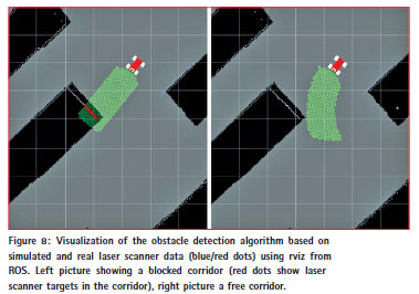
As stated above a laser scanner was used as base for the obstacle avoidance. Using these data an algorithm was developed for obstacle detection and avoidance. The main idea behind this approach is to analyze the planned route based on the steering angle of the ground vehicle in a safety corridor for possible obstacles which are detectable in the laser scanner data. Based on this identification and categorization of obstacles a decision is made to either interrupt the movement or execute automatic re-planning with an avoid and detour maneuver.
The implementation of these algorithms was achieved using the simulation environment as a development and visualization help as well as verification on the UGV. The simulation environment cannot only be used to support the development but also to provide abstract visualization of the autonomous functions of the system during operation (see Figure 8).
UGV path tracking
Since the proposed scenario does not require dynamically created routes, a preplanned path was favored instead of on board planning. Therefore the navigation problem for the UGV can be reduced to accurate path tracking, defined by a number of target points. For this purpose a geometric algorithm has been developed, based on local information of the UGV only. In every controller iteration, the relative vector between the robot frame and the next target point, the target vector, is calculated within the local robot coordinate frame. The length of the vector is equivalent to the distance to the target and is therefore used to calculate the target velocity of the robot. The target steering angle of the car-like robot is determined from the angle between the target vector and the heading vector of the robot (see Figure 7).
On the one hand this approach is capable of reaching target points and on the other hand can compensate inaccuracies in the mechanics of the robot. The vector approach also allows an easy integration of the obstacle avoidance. In presence of an obstacle, the target vector can be rotated according to the size of the obstacle, which allows an easy obstacle by-passing.
Since the proposed method is not capable of reaching targets within the turning radius of the robot, the approach has been extended by maneuver capabilities. Once a target is situated in the circle centered by the instantaneous center of curvature and with the radius defined by the minimal turning radius of the robot, a backwards maneuver is conducted using the opposite steering angle.
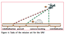
UAV route planning and UGV camera tracking
A route planning for the UAV was developed to support the demonstration foreseen in the project. This planning is based on waypoints to assure a continuous tracking of a moving target, i.e. the UGV, based on image based marker detection. The coordinates in the image frame are transformed into geocoordinates based on the attitude, the GPS coordinates and camera information. If the detection fails, e.g. if the UGV is obstructed, the UAV automatically reinitializes itself and tries to reacquire the UGV.
On this mission the UAV starts to search for the UGV from a defined position. As soon as the target is acquired the camera will be steered to keep the target centered in sight. The camera will automatically track the target as long as possible. If the UGV moves out of camera range, the UAV will follow the UGV thereby ensuring the availability of a video transmission showing the UGV as well as providing a possibly optimal data relay from the ground station to the UGV.
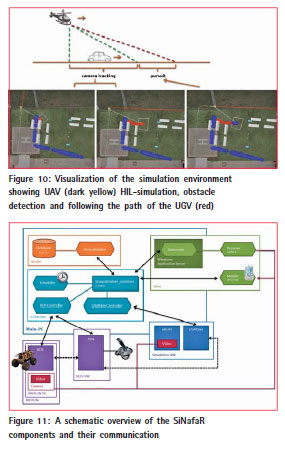
Figure 10 depicts the stationary UAV in the top left corner (dark yellow) tracking the UGV (red dots) with the camera (camera footprint can be seen as a square projected on the surface). The right picture shows the pursuit of the vehicle when it is going to leave the tracking area to keep the target in sight.
Groundstation and Human- Machine Interface (HMI)
The ZfT contributed its knowledge and expertise in teleoperation, communication, simulation and human machine interfaces (HMI).
Framework
Figure 11 shows a diagram of the SiNafaR architecture. The left upper box is the main PC where the Java-written groundstation software runs structured by the model-view-controller pattern:
• The model is a SQLite database which is connected to the central library groundstation common.
• The view is the human machine interface described later.
• The controller part consists of the central library, a scheduler, which takes care of the different tasks (patrols, interventions and actions) and controllers for tethering the mobile agents (ROS Controller) and the simulation (USARSim Controller).
The mobile agents are displayed at the bottom left corner: The first one is for the robot MERLIN with its operation system ROS and its camera. The next box depicts a virtual Ubuntu PC where ROS is also installed. It is used to teleoperate either the real robot or the virtual agent which only runs in the simulation. The simulation is also a virtual machine with the software USARSim, which will be described later. In a second program the simulation environment is displayed and a video stream is generated. So, both the robot camera and the simulation environment can create a video stream which can be displayed in the HMI.
The ZfT has developed a special communication framework responsible for exchanging data with a userdefined number of agents. Hereby the main concern was robustness and easy reusability. The client library can be used as a java packet in every other java project and is also compatible to Android. Of course, communication is a critical part in this framework. To illustrate that, a short example is given: If e.g. one of the robots reached its desired position, the controller of the robot issues an update command to the groundstation, which in turn distributes the command to all the other connected components. The scheduler can start the next action while the HMIs displays this event to the user.
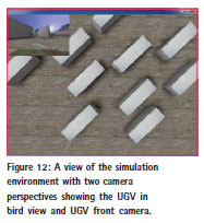
Another important part of the SiNafaR project was the integration of a simulation environment. For this purpose the team chose USARSim (Unified System for Automation and Robot Simulation [12]), a high-fidelity simulation of robots and environments based on the Unreal Tournament game engine. After configuring USARSim for the SiNafaR purpose, arbitrary mobile agents (UGVs and UAVs) can be modeled in freely configurable settings close to reality. That enables testing algorithms for path planning, mapping and obstacle avoidance. Furthermore, it helps to determine a perfect video setting for the surveillance scenario by simulating virtual easy configurable cameras, which is shown in figure 12 as an example. Here the flying perspective of an UAV is shown together with the view of a mobile agent. This facilitates and accelerates development.
Human-machine interface (HMI)
Human machine interaction describes the whole clash of humans with machines from a simple on-off-switch to a complex steering mechanism. It is a complex research field, especially if an untrained user needs to control several heterogeneous autonomous agents as it is the case in the project SiNafaR. Of course software ergonomics is very important. But crucial for the user who controls one or several robots is his situation awareness. That means wether the user realizes the actual situation, interprets it correctly and projects it to the near future. The ZfT had already done a lot of research on this topic (e.g. [14]). Along with the described general criterias, the other main target was meeting the requirements profile of the civil defense industry. Interviews with the prospective user group, realized in the collaboration with the project partner Wilkon e.K., showed that security and easy usability had absolute priority. The user interface was redesigned in several iterations of an evaluation circle where partners contributed their practical experiences. In figure 13 the main view of the HMI is shown. The largest space is reserved for a map in the right upper corner, in which the positions of all entities and their planned paths are clearly visible. This ensures a high level of situation awareness, because future behavior can be predicted. Clicked entities are also marked in the table views and vice versa. On the left side, the possible patrols, interventions and actions are shown to ensure quick access to them. This apportionment was one key result of the interviews with the Wilkon specialists. The last window part is the guard book, where all important events are shown. Technically, the HMI which is used in the SiNafaR project [13] is based on RAP (Rich Ajax Platform) and kept strictly modular, so many different scenarios can be covered. To show its practicability the appealing GUI for planning and supervising multi-robot systems was adapted for different kinds of interfaces (computers, mobile phones and tablets). The users can change the arrangement to their personal and operational needs, by simply changing the sizes and opening/ closing tabs. Also a set of predefined perspectives is available, so the user can switch them depending on which display he uses. If he uses a mobile device, a smaller amount of windows is selected. Another example is to use a second monitor where the different camera perspectives are displayed.
Final demonstration event
At the end of the project a final demonstration event was planned and conducted. The final demonstration event contained typical elements of a surveillance scenario (Figure 14). The routes between control points are pre-defined. The static control route for the UGV can be paused at any time to divert to additional control points of interest. The UAV is able to follow to the UGV autonomously to provide an additional bird view or can also be used separately.
1) The UAV is ordered by the ground station to patrol at point 3 and search for the UGV. The UGV is identified by the matrix marker.
2) The UAV is ordered to follow the UGV autonomously. The UGV is ordered to follow the pre-planned control route. Obstacles are detected and avoided
3) Pausing the control route at point 4. Tracking and pursuit by UAV is stopped. UGV and UAV can check individual POI. After that, both are ordered to return to point 4.
4) UAV re-aquires the UGV and the control route is continued.
The ground station coordinates all actions between UGV and UAV. The pose of each autonomous robot can be tracked on the control center as well as with mobile devices like tablet computers. Additionally, the video streams of both robots are supplied to the users. For the demonstration two tablet computers have been used to visualize the overview map with the moving robots or the transmitted video view.

Conclusion
In the project a GPS-RTK solution with moderate costs for mobile robotics has been integrated, various methods for GNSS fault detection and quality monitoring have been proposed and partially implemented. A GPS/odometry coupling has been successfully introduced into the navigation stack of the UGV. A highperformance radiolink has been developed by project contributor EADS Innovation Works. ZfT developed a browser based HMI interlinked with both UGV and UAV providing application centric control of the autonomous systems for non-professional human controller. The components of the system are available in a simulation environment including simulated video streams and ROS based HIL operations.
Besides developing a demonstrator study for the surveillance scenario described above, the project has achieved many results, which can be used for future projects in different kinds of application areas:
• The project showed possibilities to reduce ressources and training costs for controlling and coordinating heterogeneous multi-agent systems
• Realisation of an HMI which can be extended to further fields of teleoperation
• Identification of requirements and technologies for the future admission and certification of small cooperating multi-agent systems in the civil sector
• Combination of existing technologies to increase robustness and security of the systems to enable a future admission
Hereby many different applications are possible, e.g. surveillance of grounds or objects, measuring and revising parameters in large areas and mobile exploration systems.
Based on the loadout capability and the closedness of the used helicopter platform (especially regarding the autopilot) it was not possible to demonstrate the localization approach as well as the obstacle avoidance on the UAV. However, the results of the GNSS localization are transferable to UAVs in general To provide reliable detection of obstacles in all possible movement directions of a UAV improvements in the miniaturization of sensors are essential. Camera based systems cover a wider range of view than laser scanner and have already reached the proper dimensions. But like most optical systems they suffer from interferences due to the environment, e.g. sun glare, rain, snow, fog, smoke, etc.
The initial goal to include the detection of faulty GNSS signals in the demonstrator could not be achieved because of restrictions in the COTS receiver hardware. Innovative extensions in advanced GNSS receiver hardware should be possible in this field and should be investigated in a further project. Also, the robustness should be further extended and increased to reach the goal of a safe navigation. This would ease control for the user and allow new applications.
Acknowledgment
This article was originally published as part of the ENC2013 proceedings. Further informations regarding the conference are available on the webpage www. enc2013.org. The project ran from late 2010 to January 2013 as a cooperation of Fraunhofer IIS, University of Wuerzburg, Zentrum für Telematik e.V., EADS Deutschland GmbH und Wilkon e.K. The authors would like to thank all involved project partners. Special thanks go to the “Staatsministerium für Wirtschaft, Infrastruktur, Verkehr und Technologie” of Bavaria, Germany, financing this project.
References
[1] http://www.ros.org, ROS (Robot Operating System)
[2] http://www.onetalent-gnss.com/ ideas/usb-hw-receivers/yuan10, Yuan10 OneTalent Gnss
[3] http://www.rtklib.com/, RTKLIB: An Open Source Program Package for GNSS Positioning
[4] http://www.pmdtec.com/news media/ video/camcube.php, CamCube: A time of flight camera from pmdtechnologies gmbh TM
[5] http://en.wikipedia.org/wiki/ Kinect, Kinect from Microsoft: A depth image sensor
[6] http://www.hokuyo-aut. jp/02sensor/07scanner/utm 30lx.html, UTM-30LX: A laser range finder from Hokuyo Automatic Co. LTD
[7] http://www.navxperience.com/ products/, 3G+C: A GNSS antenna developed by Fraunhofer IIS and distributed by navXperience gmbh
[8] D. Eck and M. Stahl and K. Schilling, ’The Small Outdoor Rover MERLIN and its Assistance System for Tele-Operations’, Proceedings of the 6th International Conference on Field and Service Robotics 2007, Chamonix, France
[9] D. Eck and K. Schilling, ’Tele- Operator Assistance Systems for Small Rovers’, Proceedings of International Defense and Security Conference (SPIE) 2008, Orlando, USA
[10] L. Patino-Studencka, G. Rohmer and J. Thielecke. Approach for detection and identification of multiple faults in satellite navigation. Position Location and Navigation Symposium (PLANS), 2010 IEEE/ION, pages 221-226. IEEE, 2010.
[11] R. Heß and M. Fritscher and M. Krauss and K. Schilling,’Setting up a Surveillance System in the Civil Domain with Cooperating UAVs and UGVs Multivehicle Systems’, Multivehicle Systems 2012, Volume 2 Number 1 pages 19-24
[12] S. Carpin, M. Lewis, Jijun Wang, S. Balakirsky, and C. Scrapper. Usarsim: a robot simulator for research and education. Robotics and Automation, 2007 IEEE International Conference, pages 1400–1405, 2007.
[13] M. Fritscher, R. Heß and K. Schilling ’Generic network-based infrastructure and a browser-enabled rich client HMI’, Zentrum für Telematik 2012
[14] F. Driewer, M. Sauer, and K. Schilling. Design and evaluation of a teleoperation interface for heterogeneous human-robot teams. Design and Evaluation of Human- Machine Systems (HMS), 2007.


 (2 votes, average: 4.50 out of 5)


Leave your response!