| GNSS | |
Potential use of GBAS techniques to improve SBAS signal quality monitoring
In this paper, Space Based Augmentation System (SBAS) and Ground Based Augmentation System (GBAS) are compared regarding their specifications, architectures, status and advances with an introduction to the target service levels |
 |
|
 |
|
 |
|
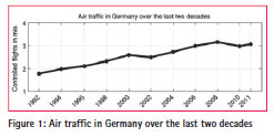
From 1992 to 2011, air traffic grew by approximately 72% in Germany [1] which is equivalent to a yearly increase of about 4%. As air traffic continuously increases, ground infrastructure like airports, number of runways and necessary capacity of air traffic routes need to grow too. To enable safe (automatic) guided precision approaches also under reduced visibility conditions, systems like the Instrument Landing System (ILS) and Microwave Landing System (MLS) exist. These systems provide a good and reliable solution; however, they have the same limits in terms of cost, ability to support simultaneous landing approaches, flexibility in waypoints and area navigation. Thus, a need for systems that can be used for enhanced precision approaches within a local, regional or wide service area rose. In aviation, GPS/ Receiver Autonomous Integrity Monitoring (RAIM) is used for en-route navigation down to non-precision approaches.
However, this technology has two limitations for precision approaches. First, the accuracy of GPS as standalone is not sufficient enough, and the second, integrity of the measured position is not available. To overcome these two limitations, several concepts, SBAS, GBAS and RAIM (which is not considered further in the context of this paper), are accepted by the aviation industry and the International Civil Aviation Organisation (ICAO).Though these systems need GPS range measurements as inputs, and produce range corrections as output, along with the integrity information, they vary strongly in actual realization. This paper first presents these two systems for their architectures and operation. Second, it focuses on EWF monitoring in order to improve the detection capabilities by reducing false alarms driven by multipath. Some ideas of GBAS SQM techniques are adapted to the need of SBAS by using EGNOS as an example.
Augmentation systems – SBAS and GBAS
SBAS and GBAS are the two main augmentation systems using navigation satellites that support SoL applications. SBAS supports wide-area or regional augmentation through the use of additional messages broadcast by geostationary satellites, whereas, GBAS supports local (typically an airport area) augmentation through the use of terrestrial radio messages with a Very high frequency Data Broadcast (VDB).
System standardization
SBAS as a wide area augmentation system and corresponding aviation user equipment are standardized, e.g., in ICAO SARPS Vol.1 Annex 10 [2] and RTCA DO-229D [3] to enable not only interoperability between the airborne receivers, but also between various SBAS systems. Standards for GBAS, also called Local Area Augmentation System (LAAS), and user equipment can be found. (For e.g., in [2, 4, 5, 6, 7 and 25]).
Basic architecture
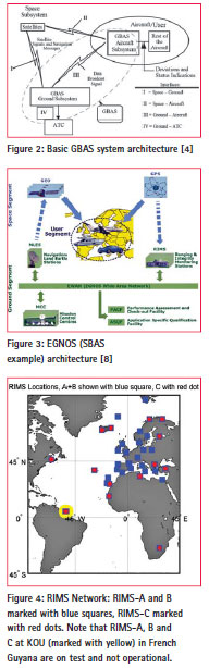
GBAS as a local augmentation system (shown in Figure 2) used at airports utilizes four antenna receiver combinations located in a 5 km radius around the furthest supported landing threshold point (considering precision approaches). The GPS L1 frequency measurements and navigation messages are sent to a central GBAS station inclose vicinity. The station is equipped with redundant hardware to compute a single set of corrections and to provide integrity by ensuring the correctness of the broadcast corrections. These corrections as well as data related to the approach segment are broadcast via VDB, and also verified at reception via the internal VHF receivers. Antennas, receivers and central GBAS station as well as the broadcast units are considered as GBAS Ground Subsystem.
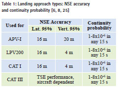
On the other hand, SBAS antennas are distributed within the entire wide service area and beyond. Since it is a wide service area, the ionospheric delays can have significant variations inducing different error ranges even in the undisturbed scenario. In order to mitigate these errors, dual frequency reference antenna receiver combinations are used. Due to the wide distribution (e.g., European Civil Aviation Conference (ECAC) service area) of the reference stations, a network is needed to deliver the recorded data to centralized processing facilities which generate the set of corrections. GEO stationary satellites (GEO) and their corresponding uplink stations are used to broadcast these corrections over a wide service area.
There are several SBAS that are either operational or under development: e.g., US Wide Area Augmentation System (WAAS), EGNOS in Europe and Multifunctional Satellite Augmentation System (MSAS) in Japan, along with the Russian System for Differential Correction and Monitoring (SDCM) and the Indian system GPS Aided Geo Augmented Navigation (GAGAN) under development.
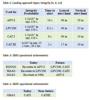
In EGNOS (cf. Figure 3), the reference stations (Ranging and Integrity Monitoring Stations (RIMS)) used for computing the GPS range measurements are widely distributed. Current EGNOS RIMS network configuration consists of 37 sites, equipped with two types of RIMS. RIMS-A and RIMS-B antenna receiver combinations are used for two independent data processing channels to meet the needs of SoL constraints. In addition, in 14 of those sites, a RIMS-C is installed to monitor the GPS signals for wave form deformation (cf. Figure 4).These site observations are distributed via the EGNOS Wide Area Network (EWAN) to the Mission Control Centres (MCC). The computed corrections from MCC are then sent via Navigation Land Earth Stations (NLES) to GEOs for broadcast.
Service levels and achievement status
For civil aviation users, the international landing categories, approach types and corresponding performance needs are specified in detail, e.g., in Figure 6.
Following the performance requirements, the existing operational SBAS systems achieve different approach categories. While WAAS achieves RNAV operations with Localizer Performance with Vertical Guidance (LPV) to 200 ft. minima in the US National Airspace, EGNOS currently achieves APV-I service level for most European countries.
The goals for GBAS are set to precision approach categories CATI and CATII-III. While GBAS CATI stations are already in operation in various countries, GBAS CATIII stations are about to be certified and become operational in the next years.
Applying GBAS techniques to improve EGNOS SQM performance
As GBAS is preparing to achieve CATIII service performances, it has adapted its SQM techniques for better performance. Some of these approaches can be tailored to improve SBAS, in particular EGNOS SQM.
SV-19 failure – fi rstoccurrence of EWF
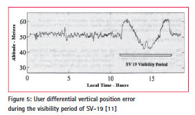
The GPS satellite SV-19, using PRN19, was launched on October 21, 1989 and declared operational on November 14. It is assumed that after approximately 8 months in orbit, an anomalous condition developed that resulted in carrier leakage in the observed L1 signal spectrum which is normally carrier suppressed [9]. The first evidence of significant end-user impact of the failure was in March 1993 during differential GPS landing system tests by Trimble. Followed by this, various tests with differential L1 C/A equipment were performed and offsets of 2 to 8 meters were reported if SV- 19 was included in the position solution depending on different types of differential GPS loop architectures [10] (c.f. Figure 5). The source of the error was analysed and identified by different institutions, leading to its correction by switching to the satellites on-board redundant signal transmitting hardware on January 3, 1994. However, during the complete time span between fault onset and fault mitigation, the satellite was set to healthy.
Since it cannot be ensured that such a failure will not occur anymore and the induced error by the user depends on the implementation of the GPS tracking loop architecture, monitoring for SV-19 like failures is needed for augmentation systems which support SoL application. The phenomenon of SV-19 events is termed as EWF because of their unpredictable and varied nature of impacts for different differential users.
2nd Order step (2OS) threat model
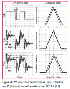
The ICAO adopted the 2OS threat model, developed in [12, 13], to describe potential EWFs on GPS L1 frequency. The model is capable of creating dead zones, distortions and false peaks on the receiver correlation peak as observed during the SV-19 failure.
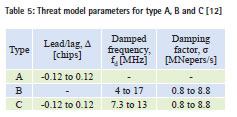
It is modeled via three threat types A, B and C with three parameters lead/lag Δ, damped frequency fd and damping factor σ.The range of the underlying parameters is shown in Table 5.
Current state of EWF monitoring in SBAS
As of today, monitoring for EWF is done within WAAS and EGNOS using the 2nd order step model as threat model. Both these systems have Novatel GII receivers [14] at their reference stations. WAAS uses the Alpha metric [15, 18, 26] algorithm and EGNOS applies the delta ratio algorithm [16, 17]. However, in EGNOS, it is desired to reduce the false alarm rate impacting the availability performance. Most of the false alarms originated due to local multipath effects at receiver antenna site, inducing similar erroneous behaviour in the receiver correlator as with an EWF. Therefore, by taking EGNOS as an example, techniques to reduce the number of false alarms are explored.
As mentioned before, GBAS evolves to serve CATIII automatic landing approaches, and several improvements including the EWF detection/Signal Quality Monitoring are envisaged to meet the tighter integrity and false alarm bounds required by CAT III [19, section IIC]. To achieve this, the GBAS community utilized improved SQM techniques also described in literature. These modernized EWF detection methodologies can be adapted to the existing SBAS implementations, to improve their SQM availability performance, i.e., in terms of minimizing false alarms without impacting the missed detections.
Used algorithms for SQM
Various methods are developed and described in literature, for which most require supplementary reference receiver correlator samples besides the tracking pair.
• CCC [20] (without supplementary correlator measurements)
• SQM2b [12, 21, 22]
• Delta Ratio Tests [16, 17]
• Alpha Metrics [15, 18]
• SDM [23]
• …
The realisations of these algorithms must be capable of protecting all ICAO accepted user receiver designs and must be robust to variations in receiver pre-correlation filters [21]. Without sticking to a single algorithm, this paper discusses a method to improve measurement quality of correlator samples that augment detection of EWF for SBAS.
The effect of multipath on correlator measurements
Multipath is considered as the driving factor for high false alarm rates for the algorithms detecting EWF. This is because both, multipath and EWF produce similar effect on code tracking, as shown on the right side of the correlation function (c.f. Figure 7). As shown, the distortion of the triangular shape due to multipath or EWF can lead to a similar correlator measurement output.
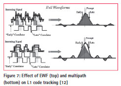
Therefore, for all EWF detection algorithms based on correlator outputs or even pseudo-ranges, the minimization of multipath leads to a higher measurement quality and as a direct follow to a lower false alarm rate.
To meet the stringent accuracy requirements for CATIII landing approaches, various multipath limitation or mitigation techniques are applied to GBAS. Some could be directly transferred to SBAS. The next chapter presents an approach of mixed antennas to reduce correlator noise for low elevations in order to lower the false alarm rate for SQM. To achieve this, an analysis is performed by replacing some of the currently used choke ring antennas by a different antenna type, called dipolearray antenna.
Mixed antenna types for the existing EGNOS RIMS-C sites
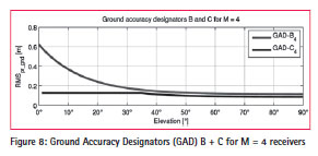
GBAS CATIII stations have to provide a significantly better performance, especially for low elevation satellites, compared to the GBAS CATI stations or to existing SBAS. For CATIII approaches, the GAD-C curve is used while for CATI approaches, GAD-B is seen as sufficient (cf. Figure 8 ) [19].
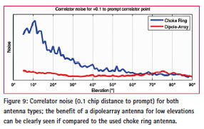
Better performance at low elevations, especially in the presence of multipath cannot be achieved with a commonly used choke ring antenna. Therefore, more expensive but more accurate dipolearray antennas are preferred.
At present in EGNOS, the number of RIMS-C stations is limited only to 13 in operation. Therefore, in this paper, a mixed antenna scenario or mixed RIMS-C network is considered by partially replacing the existing choke ring antennas by the dipolearray antennas. The analysis is carried out based on the performance of real data of both antenna types mounted in close vicinity, on Thales Alenia Space facility roof top in Stuttgart, Germany. By applying the observed properties of these antennas in a multipath rich environment on the RIMS-C network, using simulations the performance in terms of correlator noise, including multipath is analyzed. In the current EGNOS implementation, in order to monitor a satellite (monitorability condition), i.e., to provide corrections and integrity information, at least one RIMS-C [24] and two RIMS-A and B observations are needed for the given satellite. Thus a single RIMS-C is sufficient to determine EWF. However, this condition can be seen as the most critical (critical condition) in terms of to the susceptibility to false alarms. If more than one RIMS-C observes a satellite, a majority voting is performed (which is able to lower the false alarm rate).
Actually as shown below, the first condition applies to a significant period of time for all GPS satellites. Mitigation for the critical condition is to change the RIMS-C antennas at certain sites as described below.
The minimum elevations above which RIMS-A and B monitor a satellite are defined as 5°. For RIMS-C, the nominal configuration is used where the elevation mask varies between 10° to 40° depending on the site. The reason for the high elevation masks is the susceptibility of the existing RIMS-C antenna for low elevation multipath and the site specific multipath environment.
As a first approach, the analysis of mixed antennas in the RIMS-C network is kept simple and independent of all algorithms. The measurement noise is calculated for both antenna types for one degree elevation bins, using smoothed correlator measurements from the same type of receiver at 1 Hz, with a standard smoothing window of 100 seconds and chip distance of 0.1 to prompt. The output rate as well as the smoothing time constant and filter is consistent with existing SBAS systems.
Using a simulated GPS constellation for a side real daybased on broadcast ephemeris, the elevations to all satellites are calculated for all operational RIMS-A, RIMS-B and RIMS-C sites and the monitorability is derived. For the reason of comparability to the existing configuration, the current mask angles are kept for both antenna types in the mixed configuration.
Analyses show that only some RIMS-C sites on the outer boundary of the service area are subject to the condition that they see a satellite alone. Note that this outer boundary is not entirely coinciding with the geographical outer boundary as a result of the different elevation masks for RIMS-C antennas.
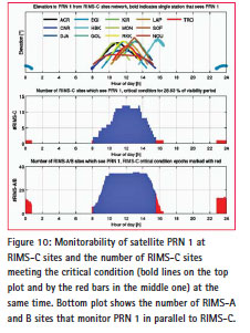
An example in Figure10 for satellite PRN 1 demonstrates the monitoring by all RIMS-C sites, and highlighting the critical condition at EGI in Island, CNR in Canary Islands and HBK in South Africa.
For PRN 1, the critical condition exists for nearly 29% of the visibility period.
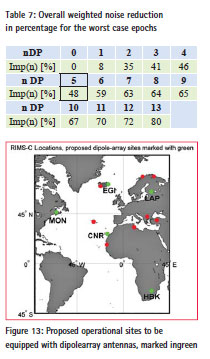
Summing up the results of all PRNs, only the five RIMS-C sites, EGI, HBK, CNR, MON in Canada and LAP in Finland encounter this critical condition (cf. Figure 13). This is consistent with the expectation that the outer sites are the most critical ones. In total, the critical condition is met for 26% of the visibility periods of all satellites.
Via error propagation, the noise on the correlator measurements for each epoch is assumed for the whole network and complete visibility duration. Even if this approach is not consistent with the current majority voting algorithm, it can be seen as an applicable approximation, because the focus of the analysis is set to the critical condition where no majority voting is performed.
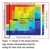
In order to find the most promising and cost effective solution for mixed antennas, an extensive simulation covering over 8,200 possible mixed antenna combinations is performed. For each combination, the highest occurring elevation θ dependent correlator measurement noise σ (θ)l,s (which is mostly the noise level when the critical condition applies and a satellite is seen with minimum elevation) is chosen to describe the combination in a conservative way. In the follow up step, the optimal combinations opt (n) for each number n of RIMS-C sites equipped with a dipole-array antennas are chosen (1). To meet this, the focus is set to find the combination that provides the best measurement quality for the critical condition identified before.
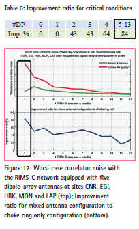
![]()
The result of the simulation confirms the sensitivity of the sites in the border of the service area. In Figure 11, the x-axis describes the number of sites that see a certain satellite under the worst case conditions, while the y-axis shows the number of RIMS-C sites equipped with dipole-array antennas. For each combination, the improvement of the worst case condition to the actual choke ring only setup is given by colour codes. Considering only the critical condition (marked with the black box), a change of five RIMS-C antennas – namely at the sites EGI, HBK, CNR, MON and LAP – to high performance dipolearray antennas (DP) improves the noise on correlator measurements for the most critical condition by up to 84% as shown in Table 6 and Figure 12. Table 7 shows the overall noise reduction for number of used dipolearray antennas (DP) as an improvement percentage ratio to the simulated current choke ring (CR) antenna configuration for the worst case correlator noises according to (2). It is weighted by the probability of occurrence prob (m) for each number of RIMS-C sites m that see a satellite during the sidereal day. It is to be noted that in the current EGNOS RIMS-C configuration a maximum of 12 RIMS-C sites can see a satellite simultaneously.
![]()
Besides, the overall noise reduction for the worst case epochs of 48% for five dipolearray antennas, the most critical situations are mitigated. Therefore, the proposed change of only five antennas can be considered as a good trade-off between noise reduction and additional costs. The location of these five sites is given in Figure 13.
Conclusion
Within the framework of the paper, both systems GBAS and SBAS are described and their current service level status is shown. The paper demonstrates that the advanced techniques of Signal Quality Monitoring of GBAS, with respect to antenna type used, can be applied to meet the SBAS needs. In this paper, SBAS is considered as EGNOS. The adaptations are also focussed to gain maximum benefit with low impact on the cost especially regarding extensive re-certification. The changes focus on miti gating multipath – the driving factor for high false alarms on EWF monitoring. Simulations confirm that it is recommended to change the antennas to high performing ones (especially for low elevations), at certain boundary reference sites of the service area.
In case of EGNOS, five such boundary reference sites are identified for the currently used elevation masks: EGI, HBK, CNR, MON and LAP. It is recommended to equip them with high performance antennas, for example, dipole-array antennas instead of the currently used choke ring antennas to reduce EWF false alarm rate.
These first simulation results are promising. Further system level studies and investigations, to evaluate the applicability of the proposed methods and applied assumptions on the existing SBAS, can affirm the proposed solutions.
References
[1] DFS, ‘Luftverkehr in Deutschland Mobilitaetsbericht’, 2011.
[2] ICAO, ‘Annex 10 to the Convention on International Civil Aviation, Aeronautical Telecommunications, Volume I Radio Navigation Aids’, International Civil Aviation Organization, Sixth Edition, July 2006, Amendment 85.
[3] RTCA, ‘Minimum Operational Performance Standards for Global Positioning System/ Wide Area Augmentation System Airborne Equipment’, DO- 229D, RTCA SC-159, 2006.
[4] ED-144, ‘High-Level PerformanceRequirements for a Global Navigation Satellite System / Ground BasedAugmentation System’, EUROCAE.
[5] RTCA, ‘GNSS-Based Precision Approach Local Area Augmentation System (LAAS) Signal-in-Space Interface Control Document (ICD)’, DO-246D, RTCA SC-159, 2008.
[6] RTCA, ’Minimum Aviation System Performance Standards for the Local Area Augmentation System (LAAS)’, DO-245A, RTCA SC-159, 2004.
[7] ED-114, ‘MOPS for a Ground Based Augmentation System (GBAS) ground facility to support CATI approach and landing’, EUROCAE, 2003.
[8] EGN-SDD SoL, V1.0, ‘EGNOS Safety of Life Service Definition Document’, European Union 2011.
[9] Edgar, C. Czopek, F., Barker, B., ‘A Co-operative Anomaly Resolution on PRN-19’, ION GPS ‚99, 14-17 September 1999, Nashville, TN.
[10] Macabiau, C., Chatre, E., ‘Impact of Evil Waveforms on GBAS Performance’, Position Location and Navigation Symposium, IEEE PLANS, pp. 22-9, 2000.
[11] Mitelman, A. M., ‘Robust Signal Quality Monitoring and Detection of Evil Waveforms’, Ph.D. Thesis, Stanford University, Stanford, CA, 2004.
[12] Phelts, R. E., ‘Multicorrelator Techniques for Robust Mitigation of Threats to GPS Signal Quality’, Ph.D. Thesis, Stanford University, Stanford, CA, 2001.
[13] Enge, P., ‘Detecting Anomalous Signals from GPS Satellites’, Global Navigation Satellite System Panel Meeting, Toulouse 18-29 October 1999.
[14] Schempp, T., Peck, S., Chou, W., Lopez, E., Hendrich, R. ‘WAAS Performance Improvements as a Result of WAAS Expansion’, ION GNSS 19th International Technical Meeting of the Satellite Division, 26- 29 September 2006, Fort Worth, TX.
[15] Phelts, R. E., Walter, T. Enge, P., ‘Toward Real-Time SQM for WAAS: Improved Detection Techniques’, ION GPS/GNSS 2003, 9-12 September 2003, Portland, OR.
[16] Bruce, A. S., Van Dierendonck, A. J., Jakab, A., Jonathan, B., Townsend, R., Wiebe, ‘Detection of GPS Satellite Signal Failures in Satellite Based Augmentation Systems (SBAS)’, ION GPS 2000, 19-22 September 2000, Salt Lake City, UT.
[17] Bruce, A. S., Quiles, A., Van Dierendonck, A. J., Jakab, A., Wiebe, J., ‘Satellite Failure Detection For EGNOS’, Proceedings of the 14th International Technical Meeting of the Satellite Division of The Institute of Navigation (ION GPS 2001) September 11 – 14, 2001, Salt Palace Convention Center, Salt Lake City, UT.
[18] Phelts, R. E. Walter, T., ‘Practical Signal Quality Monitoring for Augmentation Systems, International Symposium on GNSS, Tokyo, Japan, November 2003.
[19] Burns, J. et al., ‘Conceptual Framework for the Proposal for GBAS to Support CATIII Operations’, Navigation Systems Panel (NSP) Working Group 1 meetings, November 2009, Montreal.
[20] Shloss, P., Phelts, R. E., Walter, T., Enge, P., ‘A Simple Method of Signal Quality Monitoring for WAAS LNAV/VNAV’, ION GPS 2002, 24- 27 September 2002, Portland, OR.
[21] Phelts, R. E., Akos, D. M., Enge, P. K., ‘Robust Signal Quality Monitoring and Detection of Evil Waveforms’, Proceedings of the 13th International Technical Meeting of the Satellite Division of the Institute of Navigation, ION-GPS-2000.
[22] Phelts, R. E., Mitelman, A., Pullen, S. Akos, D., Enge, P., ‘Transient Performance Analysis of a Multicorrelator Signal Quality Monitor’, ION GPS 2001, September 2001, Salt Lake City, UT.
[23] Liu, F. Brenner, M., Tang, C. Y., ‘Signal Deformation Monitoring Scheme Implemented in a Prototype Local Area Augmentation System Ground Installation‘, ION GNSS 19th International Technical Meeting of the Satellite Division, 26-29 September 2006, Fort Worth, TX.
[24] Jensen, A., Hanssen, R., Mikkelsen, A., de Mateo, J., ‘EGNOS Performance in Northern Latitudes’, Proceedings of the 13th IAIN World Congress, Stockholm, 27-30 October 2009.
[25] Navigation Systems Panel, ‘Development Baseline SARPs Proposal’, Navigation SystemsPanel (NSP), Agenda Item 3: SARPs for GNSS Elements and Signals (GBAS), NSP May 10 / Flimsy29, 2010.
[26] Hsu, P. et al., ‘Test Results for the WAAS Signal Quality Monitor’, IEEE PLANS 2008, Hyatt Regency Hotel Monterey, California, May 5-8, 2008.


 (6 votes, average: 2.50 out of 5)


Leave your response!