| Mapping | |
High Resolution Topography database generation using Airborne LiDAR
National Remote Sensing Centre (NRSC), ISRO, Hyderabad, India has generated High resolution Digital Elevation Model (DEM) for various river beds of the country (66,000 sq. km) with an accuracy of 25 cm in height with 2D GIS database generation compatible to 1:5000 scale. DEM generation for 25,000 sq. km area of Brahmaputra river basin is an achievement |
 |
|
 |
|
Of late, efficient management of disasters is receiving utmost attention of the Governments. Flood is a major disaster in India and an average of 18.6 million hectares of land is affected annually in India, by floods. Disaster Management Support programme taken up by ISRO/DOS, provides timely support and services from aero-space systems, both imaging and communications, towards efficient management of disasters in the country. Decision Support Centre (DSC) established at National Remote Sensing Centre (NRSC) in 2002 under the ISRO Disaster Management Support Programme (DMSP) keeps a continuous watch on the flood situation in the country using the ground, aerial and space technologies.
The effect of floods can be minimized by proper management measures. Flood modeling requires accurate height information in Mean Sea Level (MSL) datum related to various aspects of rivers and floodplains. The terrain undulations in flood prone areas typically vary from 2m to 5m over a river bed hence, the inundation can run into huge extent of areas with a small amount of raise in flood water level. The efficient technology used to derive this information is from Airborne Laser Scanner (ALS) which gives very accurate Digital Elevation Model (DEM) up to a few tens of centimeters.
Airborne LiDAR
Airborne LiDAR system consists of airborne segment and ground segment. The airborne segment includes airborne platform, Ranging instrument and Position and Orientation System (POS) where as the ground system is comprised of GPS reference stations and Processing hardware and software for data synchronization and registration.
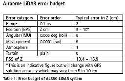
All laser-ranging operations are based on laser range finder that can measure distance to higher degree of accuracy. The system basically consists of an emitting diode that produces a Laser beam at a very specific wavelength in the near infrared region. The signal is sent towards earth where it is reflected off a feature back towards the aircraft. A receiver then captures the return pulse. Using very accurate timing mechanism with a typical accuracy in the order of 0.05 – 0.2 ns and knowing the speed of light, distance (Range) to the feature will be measured with an accuracy of one to two cm. In pulse mode method, two-way travel time of high intense short duration laser pulse between laser source and object is used for accurate estimation of range.
Range(R) = Velocity (V) Χ Time (T)/2
The accuracy with which measurements can be taken is of the order of 10 to 15 cm in elevation with dense points of upto 5 to 10 points/sq. m.
Multiple Echo
Airborne LiDAR signal also has the ability to reflect off multiple targets in its line of sight, which is most commonly observed in forest areas. The gaps between the leaves and branches allow the pulse to transmit through and reflect off obstructed upper layer while remaining pulse transmits further and reflect from lower obstructed layers including ground surface. Hence, each transmitted pulse has multiple echo system. This feature allows making measurements of the ground surface in forest areas, provides beneficial when compared to DEM generation using optical sensors.
Airborne LiDAR system for DMSP
Airborne LiDAR system is non-imaging sensor system hence it is integrated with Medium Format Digital Camera (MFDC). The combined system provides cost and time effective solution for the generation of close contours along with GIS compatible 2D spatial data. By modeling the flood inundation and estimate, monitoring floods, close contour information (0.5 m to 1.0 m) for large areas is required as database.
National remote Sensing Centre (NRSC)/Dept. of Space acquired Airborne LiDAR system integrated with Medium Format Digital Camera in 2004, for its efficiency in giving cost and time effective solution for the generation of close contours. Three models of LiDAR systems of M/s Leica Geosystems are used in the entire project life cycle (i) ALS-50 with Enerqust DC (ii) ALS50- II with RCD 105 DC and (iii) ALS-70HP with RCD 30 DC.
Floodplains area coverage
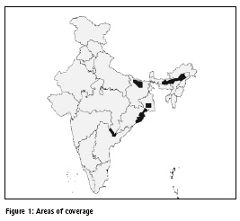
Priority areas covering approximately 60,000 sq. km. of river bed pertaining to Mahanadi, Ganga, Brahmaputra and Godavari are identified in July 2007 to take up Airborne LiDAR -DC survey for generating unique and high-resolution geospatial database. The products generated include 0.25 m he accuracy DEM in MSL, 0.5 m contours, 0.5m ortho photos and geo-database compatible to1:5000 scale.
Project execution
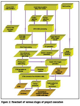
The work was carried out by initially identifying the area, flight planning for all the areas (both for LIDAR and digital camera, simultaneous data collection from aircraft and ground, preprocessing, post processing, geoid estimation, output product generation and QC. The flow chart shows the LiDAR / DC process flow from flight planning to final deliverables for a typical DMSP project:
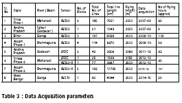
Data acquisition
Flight planning
The flight planning stage is crucial which considers the accuracy and outputs required along with the type of terrain, aircraft endurance, height of flying, distances from the GPS base station. The flight lines are generated for optimum utilization of aircraft flying.
GPS Base stations
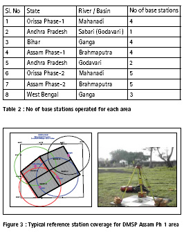
During data acquisition, DGPS base stations have been operated simultaneously in the range of 25 km of aircraft flying to improve the accuracy of the aircraft trajectory generated. Movement of field parties were planned very carefully and executed to synchronize with the aircraft operations. Added to that, field teams were kept ready in alternate area for data acquisitions in case of clouds or any other operational reasons. Field teams sometimes have to face hostile conditions such as social problems, law and order problems, local resistance etc. Subsequent to completing some areas, later on the GPS baseline lengths were increased to 50 km after studying the achieved accuracies within the flying zone thereby reducing ground survey load and acquiring data at a continuous stretch for longer distances.
Table 2 gives the number of GPS base stations operated during Data acquisition.
Aircraft operations
Aircraft operations are the most constrained part of Airborne LiDAR data collection cycle. Ministry of Defense (MOD) clearances, NOTAM for aircraft flying, timings of airfield operation, aircraft serviceability, proximity of the base to the survey area, pilots availability, availability of security officer, instrument serviceability, aircraft serviceability, area clearance, restricted areas falling in the data acquisition zone, no fly zones, time constraints in operating sensor and weather are some of the constraints that restrict productivity. Synchronization with the ground team, and if required, switching to the alternate area depending on local weather and cloud conditions were done to increase productivity. Immediately after completing the data acquisition, field checking of the data was carried out to assess the quality of acquisition and coverage. Re-flying was attempted to cover the gaps, if any.
Aerial data acquisition of 66239 sq. km in the above mentioned river basins is completed by December 2014. The areas worked out as 16,000 sq. km of Mahanadi basin (Orissa ), 25,000 sq. km of Brahmaputra basin (Assam), 18,500 sq. km of Ganga basin ( Bihar and West Bengal) and 6000 sq. km of Godavari basin ( Andhra Pradesh ). A small part of the area was flown with Large Format Digital Camera (LFDC) as there were sensor problems. Approximate number of hours flown for this task to cover this entire area is 571 hrs.
Data pre-processing and point cloud generation
Once data reaches the processing lab, preliminary checking was carried out to ascertain complete coverage and noise free data.
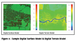
LIDAR system records line-of-sight ranges referenced to the system coordinate system, POS system logs GPS data including carrier phase information and orientation data of IMU. Pre-processing involves computing raw laser Digital Surface Model (DSM) by integrating RAW Laser data with GPS and IMU data set which are time tagged accurately.
Post-processing of airborne GPS data in differential mode with the base data improved the kinematic trajectory of the aircraft in WGS84 coordinate system to an accuracy of 5-10 cm. Differential GPS solution is blended with IMU data for obtaining Smoothed Best Estimated Trajectory (SBET) of the aircraft i.e., position and orientation of the laser scanner. Linear off-sets (lever arms) between GPS and IMU (lever arms) also applied in the solution.
The GPS time tagged laser ranging data and pulse direction which is originally recorded in LIDAR coordinate system are synchronized with POS (SBET) data and transformed each ground sample point into WGS84 earth fixed coordinate system. Post processing software uses factory calibrated information along with off-sets and misalignment angles between laser scanning system atmosphere model, and IMU for deriving point cloud in X, Y, Z for each laser pulse in WGS-84 coordinate system.
Post processing
During the preprocessing stage, the accuracy of the points is determined. The post processing to generate the products such as DEM, orthophoto and geodatabase is largely manual, laborious and time consuming. Industry support was taken to for this task.
LIDAR Classification
LiDAR classification is carried out to derive bare earth (only ground points) from LiDAR point cloud by removing the outliers and off terrain points like buildings, vegetation. The bare earth extraction is implemented through automatic and manual methods. The automatic method classifies point cloud as “ground” or “non-ground” through an automatic iterative classification algorithm and manual method is carried out to verify the correctness of the automatic classification by taking into consideration the omissions and the commissions of the process.
The terrain pertaining to the project is plain to gently undulating and it is covered with settlements, sparse bushes, water bodies such as canals, water channels, well spread ponds, rivers etc. Water bodies, river etc., create natural voids in the LiDAR datasets. Voids are also created due to non-penetration of LIDAR data to the ground in dense vegetation areas.
The complete LiDAR point cloud is DSM whereas the Digital Elevation Model (DEM) generated after filtering process.
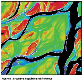
Breaklines
The breaklines are added to represent sudden variation in elevation of the ground. 3D breaklines are obtained by assigning the z-values to the 2D breaklines using the elevation data.
Geoid estimation:
LiDAR data is acquired in WGS84 datum. To convert these heights into MSL datum, local geoidal undulation modeling was carried out by collecting data by field methods.
Field Geoid
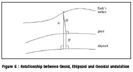
The heights measured by the LiDAR are ellipsoidal heights measured with reference to the WGS-84 elliposid. For any hydrological applications heights are required with reference to mean sea level i.e., orthometric heights. The ellipsoidal height, orthometric height (height with reference to Mean Sea Level: MSL) and geoidal undulations are related by the following formula
h = H + N
Local Geoid undulation surface generation
An inhouse methodology was developed to generate local geoid undulation model specific to project area.
Ground leveling data was acquired by collecting MSL for every 5 to 10 km at well distributed locations (by traversing from nearest Survey of India Bench Mark) on the ground by leveling. This is a laborious process in the sense that physically, on has to walk through the entire area and collect data. There are social and local problems associated with it. MSL heights by leveling are field collected and for the corresponding points the Ellipsoidal heights are derived by revisited in the lab from LiDAR bare earth surface.
A “locally best fitting Geoid model” is obtained by using these points. The model is validated using check points which have not been used in the transformation process. Kriging technique, a statistical interpolation technique, is used to estimate geoidal undulation values for the project area.
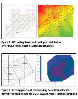
MSL datum conversion and DTM Generation
The LIDAR ground points in WGS-84 are adjusted with modeled geoidal undulation values to derive DTM with respect to MSL. The LiDAR points (in MSL) together with breakline data is used to generate Digital Terrain Model (DTM). The DTMs are generated in ASCII, GEOTIFF and LAS formats.
Contour Generation
Contours with 0.5m interval were generated using the bare earth DTM and breaklines. the requirement of the project is to generate 0.5m interval contours, every 5th contour (every 2.5m) is an index contour.
Orthophoto Generation
An unrectified aerial photograph will not show features in their correct locations due to displacements caused by the tilt of the sensor and by the relief in terrain. Ortho rectification transforms the central projection of the image into an orthogonal view of the ground, thereby removing the distorting effects of tilt and terrain relief. Generation of orthoimage uses DTM from filtered Airborne LiDAR data, images collected by Digital camera, exterior orientation parameters from GPS and IMU and interior orientation parameters from the factory calibration report of camera.
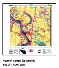
2D mapping
The 2D mapping is carried out for the entire area in the GIS environment using orthoimages.
A standardized 68 layers for the project is created with layer names, colour, line weight etc. Each tile of map covers 4Km X 4Km area.
Deliverables
All the data is delivered as 4Km X 4Km standard tiles in UTM projection with X, Y in WGS84 and Z in MSL. 3D geospatial database for entire area is prepared from Airborne LiDAR-DC data. This data consists of DEM in 5m Χ 5m grid, contours in 0.5 m interval, Orthoimage and Planimetric data. A map template consisting of graticules, north arrow, scale, legend, index etc., is standardized for all DMSP projects.
Accuracy
Quality checking and control:
The Quality Assurance / Quality Control refer to the aggregate of activities that aims at ensuring that the end product of a production process meets quality requirements of the project. The quality control for LIDAR-DC project of Disaster Management Support Programme (DMSP) is a critical component in meeting project objectives and specifications. Huge volumes of LIDAR/ Digital camera data are processed and hence stringent QC procedures are indispensable in meeting project requirements.
The quality control is implemented in two parts i.e., In-process QC and Final QC. The In-process QC is done during course of production and at end of each stage of the production activity and final QC is carried out at the end product/deliverable stage and certified by QC before submitting to the end user.
Data Accuracy Evaluation
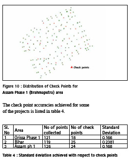
The vertical accuracy of the field geoid and Digital Terrain Model (DTM) has been validated using the well distributed check points. The table summarizes the results of the data evaluation for vertical accuracy.
The check point accuracies achieved for some of the projects is listed in table 4.
Conclusions
High resolution DEM with MSL heights and maps were generated using Airborne Laser Scanner – Digital camera system having an accuracy of 0.25m in height. Geo-database was also collected using 0.5m GSD ortho photos generated using Medium format Digital camera (MFDC) which is associated with the ALS system. An extent of 66,000 sq. km database was collected for the river beds pertaining to Mahanadi, Ganga, Brahmaputra and Godavari in the states of Orissa, Assam, Bihar, West Bengal and Andhra Pradesh which is serves as a base data for flood and other disaster related applications. Real time flood inundation modeling can be generated using this database by supplementing with other information. This is a unique project first time in India covering such a large extent of area with high accuracy, serves to predict flood extent and save precious human life by providing early warning, in particular to Brahmaputra river basin of Assam state.
Another 77,000 sq. km project is being taken up as phase II of this project under DMSP of ISRO/DOS covering other themes such as landslides, urban floods as well.
Acknowledgements
The authors acknowledge the support provided by the present Director of NRSC, Dr YVN Krishna Murthy and former directors Dr V K Dhadwal, Dr V Jayaraman, Dr RR Navalgund and Dr K Radhakrishnan. The support of Dr V S Hegde, former director EOS/DOS, Shri K. Kalyanaraman, former GM, AS&DM and Dr V Bhanumurthy, AD, NRSC are duly acknowledged. The direction provided by the decision making team of Sri P Srinivasulu, GD, AS&DMG, Dr S MuraliKrishnan, Head, DP&VASD, Dr G Varaprasad, Head, AO&ASD and Sri B Laxman, Manager, PP&CC are acknowledged. The authors acknowledge the contributions made by Shri K Venkateswar Rao, Manager, AS&AO and Shri S Madhusudhan Reddy, Dy Manager, Aircraft Maintenance during aircraft operations.
The Aircraft operations, Data acquisition, LiDAR Data processing, Ground surveys, Flight planning, Quality Assurance, Project planning and coordination, and budget teams from Aerial Services & Digital Mapping area are part of this work and their immense contributions are acknowledged.
References
1) Aloysius Wehr et al., “Airborne laser scanning— an introduction and overview” ISPRS Journal of Photogrammetry & Remote Sensing 54 _1999. 68–82.
2) E.P. Baltsavias “Airborne laser scanning: basic relations and formulas”, ISPRS Journal of Photogrammetry & Remote Sensing 54 _1999. 199–214.
3) Lohani, B., LiDAR Tutorial
4) http://home.iitk.ac.in/~blohani/LiDAR_Tutorial/ Airborne_AltimetricLidar_Tutorial.htm
5) Belen Burman,“ Laser strip adjustment for data calibration and verification” www.isprs.org/proceedings/XXXIV/part3/papers
6) Leica ALS system brochures by M/s Leica Geosystems
7) Bellamkonda Sadasiva Rao et al., “Evaluation of EGM 2008 with EGM96 and its Utilization in Topographical Mapping Projects” Journal of the Indian Society of Remote Sensing, June 2012.
8) K F Aleem “Geoid modeling” Geodesy article in Coordinates, Aug 2012


 (No Ratings Yet)


Leave your response!